- NXP
- SC16IS760
- SC16IS750
- UART bridge
SC16IS760 EOL: Can SC16IS750 Be Used as a Pin-to-Pin UART Bridge Replacement?
A practical SC16IS760 replacement guide covering NXP PCN 202603004DN, SC16IS750 vs SC16IS760 SPI and IrDA limits, FIFO timing, validation tests, and sourcing decisions.
Quick facts
- NXP PCN 202603004DN lists SC16IS760IBS,128 for full withdrawal with limited availability.
- The PCN lists SC16IS750IBS,128 as the replacement reference, with Last Time Buy on 20-Apr-2027 and Last Time Delivery on 20-Oct-2027.
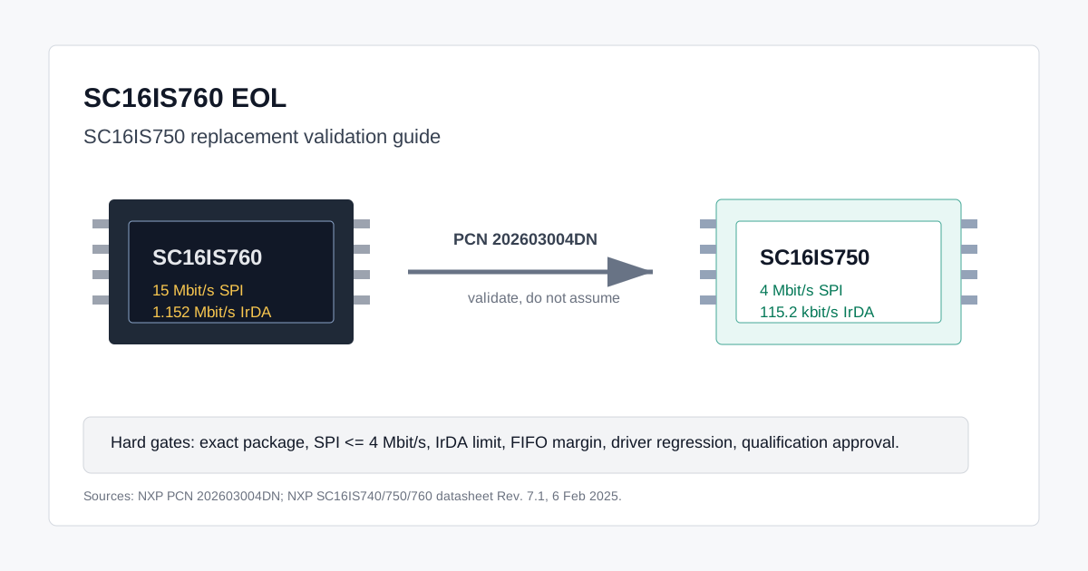
- The NXP SC16IS740/750/760 datasheet says SC16IS760 differs from SC16IS750 mainly by supporting 15 Mbit/s SPI instead of 4 Mbit/s, and 1.152 Mbit/s IrDA SIR instead of 115.2 kbit/s.
- SC16IS750 should be treated as a validation-based replacement candidate, not a universal zero-risk drop-in.
NXP PCN 202603004DN, issued on 17-Jul-2026 and effective on 20-Jul-2026, turns the SC16IS760 replacement question into a real procurement and engineering task. The PCN lists SC16IS760IBS,128 under full withdrawal with limited availability, sole-source status, a Last Time Buy date of 20-Apr-2027, and a Last Time Delivery date of 20-Oct-2027. It also lists SC16IS750IBS,128 as the replacement part reference.
That does not mean every existing SC16IS760 board can automatically accept SC16IS750 with no test work. NXP's own PCN language says replacement designations are reference information and do not guarantee the same form, fit, function, or performance before customer qualification. The better question is this: does the original design depend on the performance features that only SC16IS760 provides?
The short answer is practical but conditional. If the original design uses SPI at 4 Mbit/s or below, does not require high-speed IrDA SIR, and has enough FIFO service margin, SC16IS750IBS,128 can be a low-risk replacement candidate after validation. If the design depends on SC16IS760's 15 Mbit/s SPI path, 1.152 Mbit/s IrDA SIR, or very tight receive timing at high UART throughput, the replacement needs deeper testing or a different sourcing plan.
SC16IS760 vs SC16IS750: What Actually Changes?
The NXP SC16IS740/750/760 datasheet Rev. 7.1, dated 6 February 2025, describes the family as a single-channel UART bridge with I2C-bus or SPI host interface, 64-byte transmit and receive FIFOs, 2.5 V or 3.3 V operation, and a 16C450-compatible register set.
The same datasheet states the important delta clearly: SC16IS760 supports higher SPI clock speed and higher IrDA SIR speed than SC16IS750. In all other aspects, the datasheet positions SC16IS760 as functionally and electrically the same as SC16IS750. For replacement work, that is helpful, but the two downgraded limits are exactly where a high-throughput embedded design can fail.
| Parameter | SC16IS760 | SC16IS750 | Replacement Impact |
|---|---|---|---|
| Host interface | I2C / SPI | I2C / SPI | Same interface family |
| Max SPI clock | 15 Mbit/s | 4 Mbit/s | Main downgrade risk |
| I2C speed | 400 kbit/s max | 400 kbit/s max | No practical gain for high-throughput UART |
| UART channel | 1 full-duplex UART | 1 full-duplex UART | Same architecture |
| UART baud rate | Up to 5 Mbit/s | Up to 5 Mbit/s | Host drain path still matters |
| FIFO | 64-byte TX / RX | 64-byte TX / RX | Same buffer depth |
| GPIO | Up to 8 GPIOs | Up to 8 GPIOs | Same for SC16IS750 / SC16IS760 |
| IrDA SIR | Up to 1.152 Mbit/s | Up to 115.2 kbit/s | Risk if IrDA is used |
| Register set | 16C450 compatible | 16C450 compatible | Driver reuse is likely but must be tested |
| Packages | HVQFN24 / TSSOP24 | HVQFN24 / TSSOP24 | Package-specific pin review still required |
Representative product anchors for this article include NXP SC16IS760IBS,128, NXP SC16IS750IBS,128, NXP SC16IS760IPW, NXP SC16IS750IPW, and NXP SC16IS740IPW. The IBS and IPW variants should not be mixed at PCB level without package and pin review.
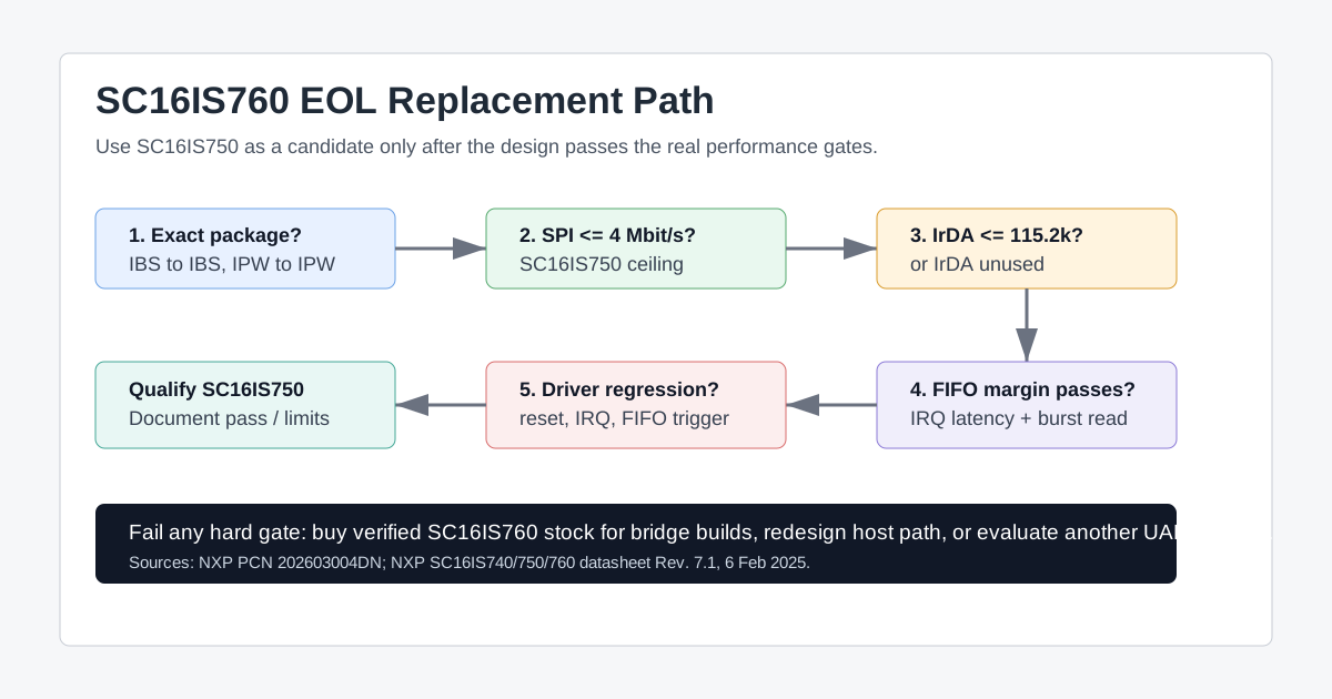
Replacement Validation Checklist Before Buying SC16IS750
Start with the exact orderable part number. The PCN entry verified for this article is SC16IS760IBS,128 to SC16IS750IBS,128. That is a package-specific path. Do not assume a TSSOP24 SC16IS760IPW board can use an HVQFN24 SC16IS750IBS,128, and do not assume all suffixes are covered by the same PCN line.
Before placing a production replacement order, engineering should run this checklist:
- Confirm the discontinued MPN, replacement MPN, package, reel suffix, and temperature requirement.
- Confirm whether the host interface is SPI or I2C in the actual product build.
- If SPI is used, check the configured SPI clock. Anything above 4 Mbit/s must be reduced for SC16IS750 and retested.
- Confirm the MCU SPI configuration uses Mode 0, as specified for the SC16IS7x0 SPI interface.
- Test the product's maximum UART baud rate, worst-case RX burst, interrupt latency, and FIFO trigger level.
- Monitor overrun, framing, and parity flags during stress traffic.
- Confirm whether IrDA is used. If the product requires IrDA SIR above 115.2 kbit/s, SC16IS750 is not equivalent.
- Verify RTS / CTS automatic hardware flow control if the product relies on it.
- Verify RS-485 direction-control timing if RTS drives the transceiver driver-enable path.
- Run a driver regression test for reset sequence, register access, FIFO trigger behavior, IRQ handling, and burst reads.
- Reconfirm internal qualification, customer approval, and regulated-product documentation requirements.
This is the practical boundary: SC16IS750 is an NXP-listed replacement candidate, not a blanket zero-code-change substitute.
FIFO Timing: Why a Slower SPI Host Link Can Matter
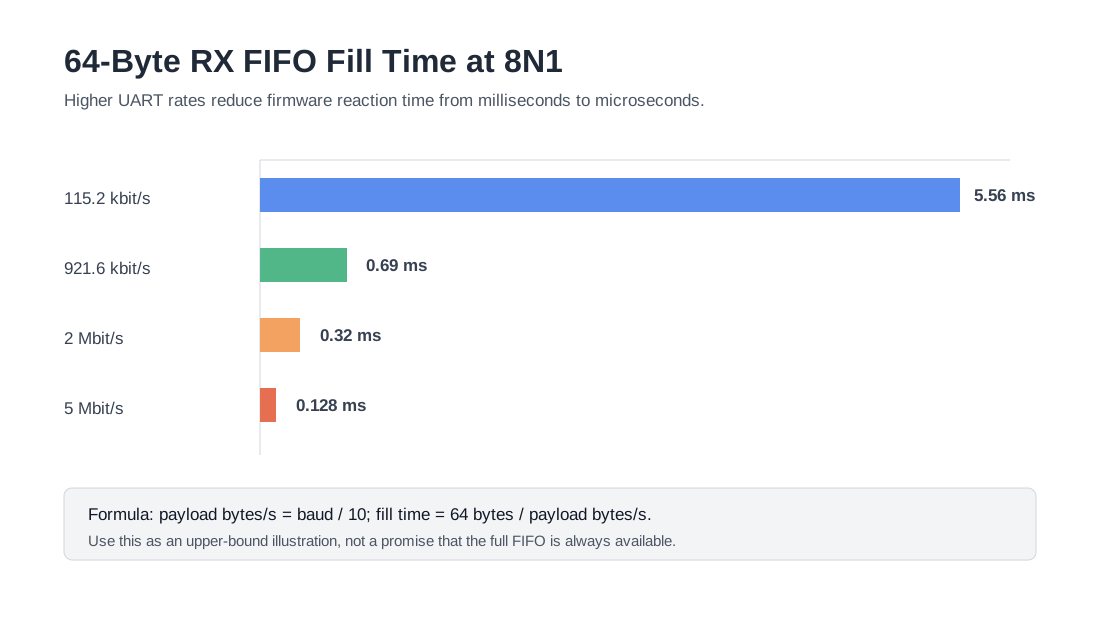
UART line rate is not the same as payload byte rate. With common 8N1 framing, each byte consumes 10 line bits: one start bit, eight data bits, and one stop bit.
payload_bytes_per_second = uart_baud_rate / bits_per_frame
fifo_fill_time_seconds = fifo_available_bytes / payload_bytes_per_second
For 8N1:
payload_bytes_per_second = baud / 10
Using the full 64-byte RX FIFO as an illustrative upper bound:
| UART Baud Rate | Approx Payload Rate at 8N1 | Time to Fill 64-Byte RX FIFO |
|---|---|---|
| 115.2 kbit/s | 11.52 kB/s | 5.56 ms |
| 921.6 kbit/s | 92.16 kB/s | 0.69 ms |
| 2 Mbit/s | 200 kB/s | 0.32 ms |
| 5 Mbit/s | 500 kB/s | 0.128 ms |
Do not design as if all 64 bytes are always available. In a real product, the FIFO may already contain data when the interrupt is serviced, and firmware still has to absorb interrupt latency, RTOS scheduling, temporary interrupt masking, chip-select setup, and SPI transaction overhead.
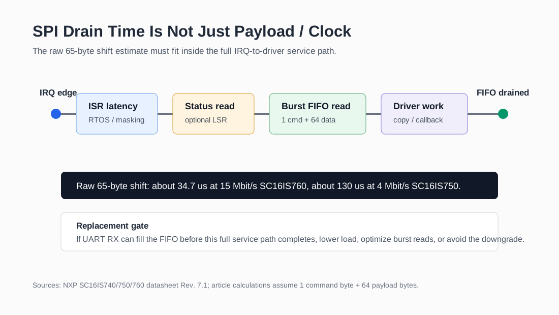
SPI Drain-Time Budget: The Missing Calculation in Many Replacement Reviews
A common mistake is to compare UART baud rate with SPI clock and stop there. The UART bridge is not a bare wire. The MCU must respond to an interrupt, possibly read status, perform a FIFO read transaction, and hand the data to the driver stack.
For a best-case burst read model:
spi_bits = 8 * (command_bytes + payload_bytes)
spi_shift_time = spi_bits / spi_clock
For a conservative firmware model:
total_service_time =
  irq_latency
  + status_read_transaction
  + rx_fifo_read_transaction
  + driver_overhead
For an illustrative 64-byte FIFO burst with one command byte and 64 payload bytes:
| Host SPI Clock | Raw Shift Time for 65 Bytes | Comment |
|---|---|---|
| 15 Mbit/s | about 34.7 us | SC16IS760 ceiling; large timing margin |
| 4 Mbit/s | about 130 us | SC16IS750 ceiling; still fast, but margin shrinks |
| 400 kbit/s I2C equivalent | about 1.3 ms before I2C overhead | Can be too slow for high-rate bursts |
This is an estimate of raw shift time, not a guaranteed total bus transaction time. The real service time also includes chip-select gaps, MCU peripheral setup, driver loops, and interrupt scheduling.
At 2 Mbit/s UART 8N1, the FIFO can fill in about 0.32 ms. A 4 Mbit/s SPI burst can shift 65 bytes in about 0.13 ms, which looks comfortable until the design waits until the FIFO is nearly full. Then the remaining budget for interrupt latency and software overhead is only about 0.19 ms. That is why FIFO trigger level, burst-read implementation, and IRQ latency matter when replacing SC16IS760IBS,128 with SC16IS750IBS,128.
Replacement Risk Decision Table
Use this table as a first-pass decision filter before release testing:
| Original Design Condition | SC16IS750 Replacement Risk | Recommended Action |
|---|---|---|
| SPI configured at <= 4 Mbit/s | Low | Validate normal regression and stress traffic |
| SPI configured above 4 Mbit/s | Medium to high | Lower SPI clock to <= 4 Mbit/s and run overrun / latency tests |
| IrDA unused | Low | No IrDA-specific issue |
| IrDA SIR <= 115.2 kbit/s | Low | Verify IrDA mode setup and interoperability |
| IrDA SIR above 115.2 kbit/s | High | Do not treat SC16IS750 as equivalent |
| UART traffic is low-rate or bursty with idle gaps | Low to medium | Validate IRQ and FIFO service margin |
| Sustained UART RX near 2-5 Mbit/s | High | Run long stress tests; consider keeping SC16IS760 or redesigning host path |
| Driver performs burst FIFO reads | Lower | Confirm transaction format and FIFO trigger level |
| Driver reads one byte per transaction | Higher | Optimize driver or reduce UART load |
| Product requires customer / regulatory qualification | Higher process risk | Treat as engineering change with documented validation |
The sourcing implication is direct. If the table says low risk, qualify SC16IS750 quickly and reserve supply. If it says medium risk, treat firmware changes and testing as part of the buy decision. If it says high risk, do not use the replacement label as permission to approve the part.
Reproducible Validation Procedure
A useful SC16IS760-to-SC16IS750 qualification run should be repeatable enough that procurement, engineering, and quality teams can all understand the result.
- Configure the MCU SPI controller to SC16IS750-safe settings: SPI clock at or below 4 Mbit/s, SPI Mode 0, and the same chip-select timing used on the target PCB.
- Generate worst-case UART RX traffic at the product's maximum configured UART baud rate. Use continuous streams, not only short command-response packets.
- Include realistic packet sizes and idle gaps if the real product is burst-based.
- Log line-status overrun, framing, and parity flags.
- Record bytes sent versus bytes received using sequence numbers or CRC.
- Capture IRQ-to-drain timing with a logic analyzer or GPIO toggle at ISR entry and FIFO drain completion.
- Capture SPI transaction length, chip-select gaps, and whether the driver reads the FIFO in a burst or one byte per transaction.
- Verify RTS / CTS under receive pressure.
- For RS-485 products, capture driver-enable direction timing if RTS controls DE.
- Run an engineering soak test for at least 1-2 hours. For stronger release confidence, run 24 hours under maximum expected traffic and temperature conditions.
Suggested acceptance language:
| Result | Practical Meaning |
|---|---|
| Pass | SC16IS750 can be qualified as a practical replacement candidate for this design. |
| Conditional pass | The design works after lowering SPI clock, changing FIFO trigger level, or optimizing FIFO reads; document the firmware change. |
| Fail | The original design depends on SC16IS760-only performance; use remaining SC16IS760 stock, locate verified inventory, or redesign around another bridge. |
Document the tested MPN, package, date code if available, firmware commit, SPI clock, UART baud, FIFO trigger level, test duration, and observed error count.
Why Use SPI to Carry UART Traffic?
The architecture can look odd at first: why use a fast SPI bus to carry data from a slower UART? The answer is that UART traffic arrives asynchronously. The bridge collects bytes in its FIFO, then the MCU drains that FIFO in bursts when the IRQ fires.
A 2 Mbit/s UART stream carries roughly 200 kB/s with 8N1 framing. A 400 kbit/s I2C host path is only about 50 kB/s before overhead and transaction cost, so it can become the bottleneck for sustained traffic. A 15 Mbit/s SPI host path can theoretically shift about 1.875 MB/s before overhead, leaving far more room to drain the 64-byte FIFO quickly.
With SC16IS750, the 4 Mbit/s SPI ceiling is still much faster than I2C, but it is a real downgrade from SC16IS760. The right conclusion is not "4 Mbit/s is too slow." The right conclusion is "4 Mbit/s must be tested against this product's real UART burst profile and firmware latency."
UART vs I2C vs SPI in This Replacement Decision
This article is not a general protocol tutorial, but the protocol choice explains the replacement risk.
UART is asynchronous, full-duplex, and point-to-point. It is common for intelligent modules that can send data at any time, including cellular, Bluetooth, Wi-Fi, GNSS, RS-485 transceivers, and industrial controllers.
I2C is synchronous, two-wire, and multi-drop. It is useful for low-speed configuration devices such as sensors, RTCs, power monitors, and EEPROMs. For a UART bridge, the target cannot push data directly over I2C; the MCU must react to IRQ and perform reads, while 400 kbit/s bus speed can restrict sustained FIFO drain rate.
SPI is synchronous and high speed, with chip select and full-duplex signaling. It is common for displays, ADCs, DACs, flash, and bridge devices that need fast burst transfers. For SC16IS750 and SC16IS760, the datasheet specifies SPI Mode 0.
Component Shortage Decision Framework
For buyers, the SC16IS760 EOL problem should be handled in tiers.
| Tier | Path | When It Fits | Main Risk |
|---|---|---|---|
| 1 | Same-manufacturer, same-family, same-package replacement candidate | Example: NXP-listed SC16IS750IBS,128 for SC16IS760IBS,128 | Lower layout and software risk, but SPI / IrDA / FIFO validation still required |
| 2 | Cross-manufacturer pin-compatible or register-compatible bridge | Useful if NXP stock is unavailable or allocation is tight | Must verify pinout, electrical limits, reset defaults, FIFO depth, SPI timing, IRQ behavior, and driver assumptions |
| 3 | Architecture change | MCU with more native UARTs, different bridge, external logic, USB bridge, or different host bus | Highest risk: PCB layout, firmware porting, EMC, thermal, lifecycle, and customer qualification |
For immediate continuity, the first procurement question is whether verified SC16IS760IBS,128 or the correct package variant can still be sourced for bridge builds or lifetime buy. The second question is whether SC16IS750IBS,128 can be qualified quickly enough to avoid relying on shrinking SC16IS760 supply. Redesign should be the third path, used when the performance boundary or qualification boundary fails.
Practical Buyer and Engineer Checklist
Before placing a replacement order, confirm:
- Exact discontinued MPN and package
- NXP PCN status, LTB date, and LTD date
- Listed replacement part and package
- Host interface actually used: SPI or I2C
- Configured SPI clock
- UART baud rate and burst pattern
- FIFO trigger level and IRQ latency
- Overrun flag behavior during stress test
- IrDA requirement
- RTS / CTS and RS-485 direction-control requirement
- Firmware driver assumptions
- Customer approval and qualification requirements
Conclusion
The most defensible SC16IS760 replacement answer is conditional: SC16IS750 can be a strong same-family replacement candidate when the existing design stays within the SC16IS750 limits. Turn that judgment into three concrete actions:
- Lock remaining SC16IS760 stock if the existing design uses SPI above 4 Mbit/s, depends on 1.152 Mbit/s IrDA SIR, or cannot absorb firmware timing changes before the next build.
- Qualify SC16IS750 if the product already runs SPI at or below 4 Mbit/s, does not use high-speed IrDA, and can pass FIFO overrun, IRQ latency, flow-control, and driver regression tests.
- Trigger redesign only when the boundary fails: sustained high-rate RX traffic, weak FIFO service margin, one-byte SPI reads, package mismatch, or customer / regulatory qualification risk.
For low-rate UART expansion, command-response modules, and designs already using conservative SPI settings, qualification may be straightforward. For sustained high-rate RX traffic, one-byte FIFO reads, strict IrDA requirements, or regulated products, the replacement should be treated as a formal engineering change rather than a purchasing shortcut.
SC16IS760 / SC16IS750 Sourcing Support
Need hard-to-find SC16IS760, SC16IS750, or other SC16IS7x0 UART bridge parts? TrustCompo can support RFQs, PCN review, package-level cross-reference checks, datasheet collection, and fast-turn sourcing for embedded and industrial BOMs.
Start with an RFQ request, a request verified stock pricing, or a shortage sourcing review for your exact MPN, package, target quantity, and delivery window.