- current sensing
- Hall sensor
- TMR sensor
- power conversion
Hall vs TMR Current Sensor Selection Guide for Power Conversion
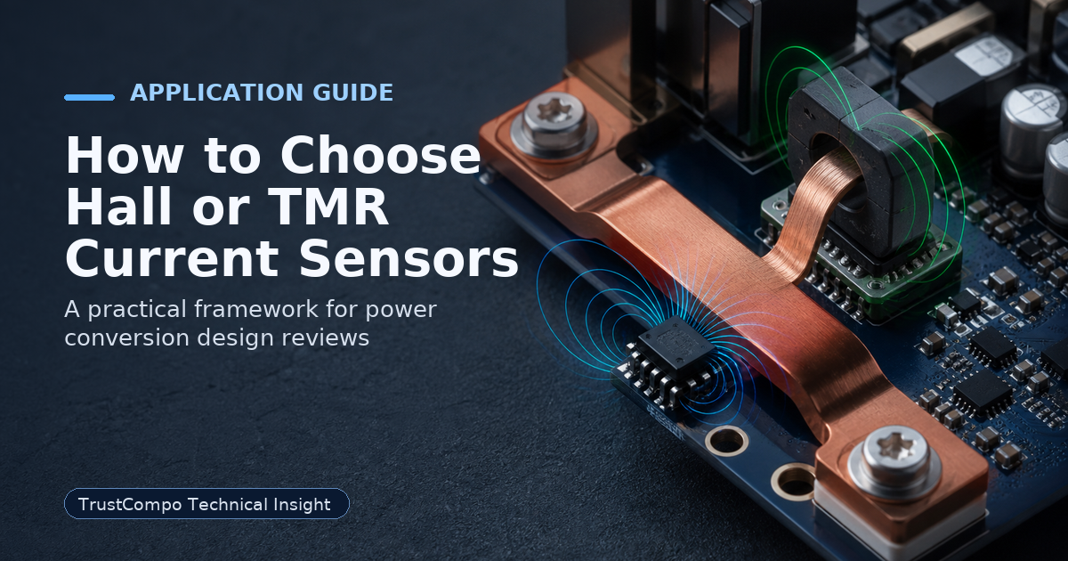
How to choose Hall or TMR current sensors for power conversion using failure mode, bandwidth, loss, geometry, offset, interface, and validation checks.
Quick facts
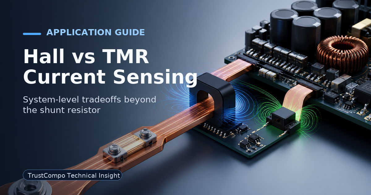
- As of August 25, 2026, the most useful first split is not Hall versus TMR alone. It is shunt, Hall iCR, Hall+coil, or TMR eCR.
- Bandwidth, accuracy, and response-time numbers are not interchangeable across architectures unless conductor geometry, calibration method, and temperature window are also specified.
- Hall remains attractive when the package already controls the current path; TMR becomes more compelling when protection latency and insertion loss dominate the decision.
- This article turns the companion system-level comparison into a device-selection workflow for OBC, DC-DC, inverter, servo, and server-power programs.
To choose between a Hall current sensor and a TMR current sensor in power conversion, start with the job the sensor must perform. If the sensor is mainly for stable AC/DC current feedback and the package should control the current path, Hall with an integrated current rail is often the lower-risk baseline. If the design is driven by low insertion loss, compact external-conductor sensing, MHz-class observability, or sub-200 ns class protection, TMR or a fast Hall+coil architecture should move higher in the shortlist.
This is not the same problem as choosing a Hall, AMR, or TMR position sensor for a motor encoder. In power conversion, current-sensor selection has to survive the real system: dv/dt, overload timing, copper loss, thermal rise, conductor geometry, common-mode stress, and production calibration. A part that looks strong in a parametric table can still be the wrong device if it solves the wrong failure mode or puts the implementation burden in the wrong place.
This article stays deliberately practical. It is built from datasheets, first-order implementation math, and design-review logic rather than a bench shootout. The device facts below are anchored to official product material reviewed on August 25, 2026. The calculations are engineering estimates used to expose tradeoffs early. The application-fit conclusions are TrustCompo engineering judgment based on those two layers, not claims of universal superiority.
If your team is still deciding whether to leave shunt sensing at all, start with the companion system comparison: Shunt vs Hall vs TMR Current Sensing. If magnetic current sensing is already on the table and the question is which architecture to approve, use this selection guide.
Fast Selection Answer
| Design priority | Start with Hall | Start with TMR | Also review |
|---|---|---|---|
| stable isolated current feedback | Hall iCR | only if compact eCR geometry is already controlled | shunt plus isolated amplifier if precision dominates |
| sub-200 ns protection or fast fault visibility | not conventional Hall iCR | TMR eCR | Hall+coil hybrid |
| lowest implementation burden | Hall iCR | only with strong calibration and layout ownership | packaged high-current Hall |
| compact sensing around an external copper path or busbar | less natural unless package fits | TMR eCR | custom magnetic path validation |
| high-density server, OBC, DC-DC, or e-fuse node | Hall iCR for slower measurement lanes | TMR for fast, compact, low-loss lanes | split measurement and protection architectures |
1. The Decision Baseline: Define the Failure Mode and the 3 Magnetic Lanes
The first job in current-sensor selection is not to compare part numbers. It is to define what failure mode the converter must survive and which magnetic lane actually belongs on the table. This baseline step prevents the whole article from collapsing into a false binary of "Hall or TMR?" when the real shortlist is already narrower and more application-specific.
1.1 Start with the failure mode, not the sensor name
The fastest way to build a bad shortlist is to begin with "Hall or TMR?" before defining what the sensor must do for the converter.
In practice, current sensing in power conversion usually serves one or more of four jobs:
- closed-loop current measurement
- fast overcurrent shutdown
- efficiency and thermal supervision
- isolation-friendly current observation at a hard switching node
Those jobs pull the shortlist in different directions.
| Primary job | What matters first | Typical winning lane |
|---|---|---|
| steady-state control and current feedback | bandwidth margin, offset behavior, drift, implementation simplicity | Hall iCR or selected Hall+coil |
| ultra-fast protection | propagation delay, fault-threshold behavior, high-frequency visibility | TMR eCR or fast Hall+coil |
| low-loss current observation in high-current paths | insertion resistance, conductor temperature rise, isolation posture | Hall iCR, Hall+coil, or TMR eCR |
| compact isolated sensing around external conductors | package size, magnetic coupling, external busbar or copper geometry | TMR eCR |
That first split prevents a common mistake: choosing a protection-optimized sensor for a metrology-oriented job, or choosing a convenient integrated Hall device for a converter stage whose real bottleneck is sub-200 ns fault reaction.
1.2 Hall is not one lane anymore
If the team still talks about "Hall current sensing" as one class, the discussion is already too coarse. The current market is more usefully split into three magnetic lanes:
| Lane | Representative anchor | Why it exists |
|---|---|---|
| Hall with integrated current rail, or iCR | TLE4971A050N5E0002XUMA1 | Lower implementation burden, isolated measurement, moderate bandwidth, package-controlled conductor path |
| Hall+coil hybrid | TLE4978R050W5OS0010XUMA1 | Hall-style isolated sensing with much higher dynamic response and fast OCD |
| TMR with external current rail, or eCR | TLE5571AE24O5IS0001XUMA1, TLI5572AE15E1E0001XTSA1 | Low insertion loss, compact isolated placement, MHz-class response, protection-first behavior |
This is the key continuity point from the companion article. The system-level piece explains why shunts lose ground; this one explains how the magnetic path splits after that decision.
The parts reviewed on August 25, 2026 make the split concrete:
- TLE4971A050N5E0002XUMA1 is the mature Hall iCR baseline with an integrated rail, typical
210 kHzbandwidth, and220 µOhminsertion resistance. - TLE4978R050W5OS0010XUMA1 is not a legacy Hall part. It is a hybrid Hall+coil device positioned for
9 MHzbandwidth and100 nsovercurrent detection. - TLE5571AE24O5IS0001XUMA1 is a TMR eCR anchor positioned for
>2.5 MHzbandwidth and sub-150 nsOCD. - TLI5572AE15E1E0001XTSA1 is the compact TMR eCR path with
>1 MHzbandwidth,140 nsresponse, and explicit dependence on end-of-line calibration for quoted temperature accuracy.
That last point matters because the choice is no longer "slow Hall versus fast TMR." The real choice is which magnetic architecture carries the least system burden for the converter you are designing.
2. Datasheet Deconstruction: 5 Real-World Parameter Traps and the Math
Many articles rank current sensors by brochure order. That is not how power teams actually make release decisions. The more useful method is to deconstruct the shortlist through the handful of parameter traps that repeatedly break power-conversion builds: speed, loss, geometry, offset, and interface behavior. This is also the section where source discipline matters most.
Read the material below in three layers:
- official device facts: bandwidth class, OCD timing, insertion resistance, package claims, and stated calibration posture from vendor material
- first-order engineering estimates: rise-time math,
I^2Rloss, offset-to-current conversion, and geometry-driven gain spread - TrustCompo judgment: which parameter should dominate the shortlist in a given converter, and which burden is acceptable for the program
That separation keeps the article useful without pretending that a datasheet table is the same thing as bench validation.
2.1 Speed trap: response time and bandwidth
Start here if the converter uses SiC or GaN, or if protection timing is part of the business case.
Bandwidth and response time are related but not identical:
- bandwidth tells you how much waveform content the sensor can reproduce
- response time tells you how quickly a fault or step event is recognized at the output or OCD path
The product families separate sharply here:
| Anchor part | Official headline bandwidth | Protection timing signal | Selection meaning |
|---|---|---|---|
| TLE4971A050N5E0002XUMA1 | 210 kHz typ. | dual OCD outputs, but not a MHz-class lane | Better as a Hall baseline than as a fast-edge observer |
| ACS724LLCTR-20AB-T | 120 kHz | mature Hall path, not a protection-speed flagship | Good reference for mainstream isolated Hall sensing |
| TLE4978R050W5OS0010XUMA1 | 9 MHz | 100 ns OCD | Suitable when Hall must compete in fast-switching power stages |
| TLE5571AE24O5IS0001XUMA1 | >2.5 MHz | <150 ns OCD | Strong protection-first TMR anchor |
| TLI5572AE15E1E0001XTSA1 | >1 MHz | 140 ns response | Compact TMR lane for space-constrained high-current systems |
Selection rule:
- If the current path is mainly for averaged control and supervision,
100 kHzto low-100s kHzclass Hall can still be enough. - If the sensor must participate in edge-rich observation or very fast fault handling, treat Hall iCR and fast Hall+coil as different lanes.
- If the architecture decision is being made by protection latency, TMR eCR usually deserves earlier attention than conventional Hall.
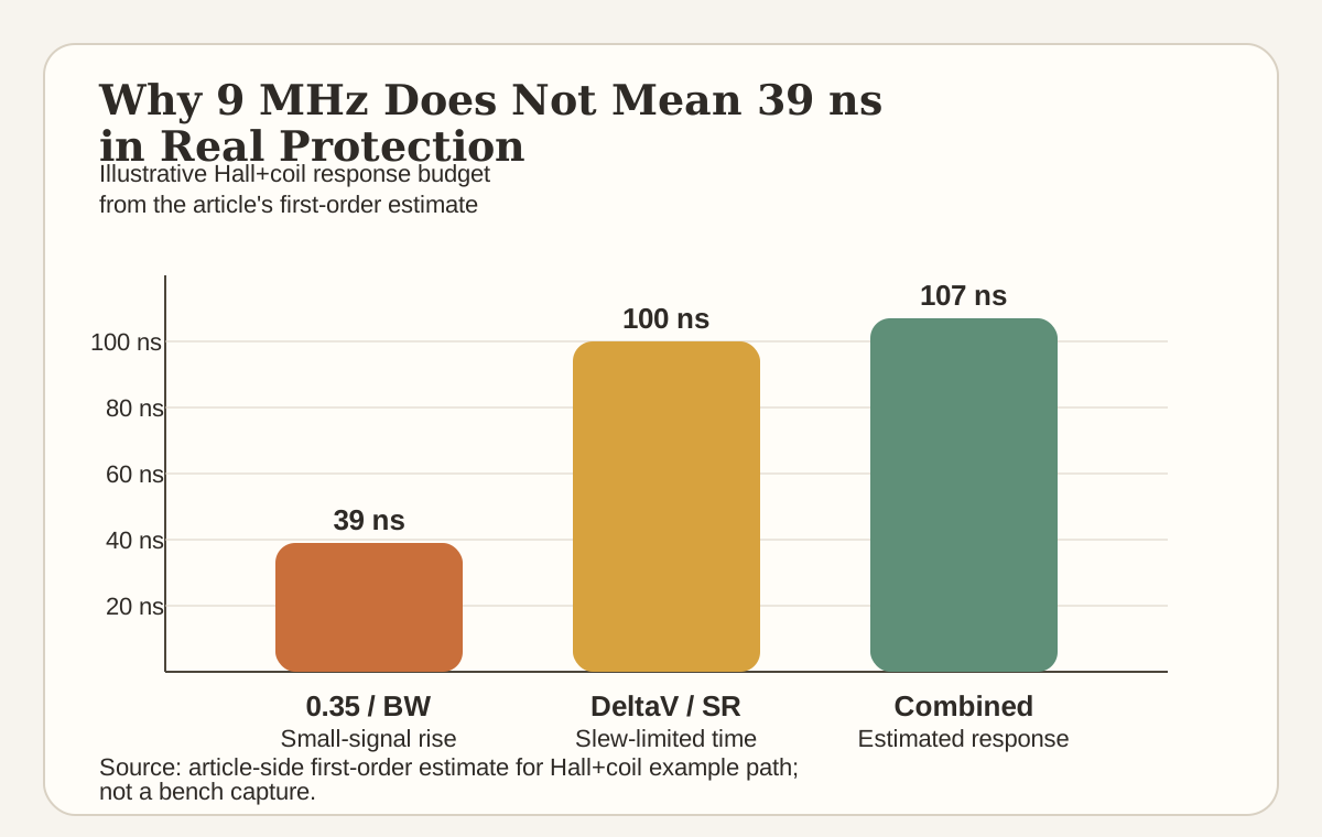
Math in action: why 9 MHz does not automatically mean 39 ns real-world protection
This is the first place where datasheet reading often becomes too optimistic. Engineers see a 9 MHz headline bandwidth and mentally convert it into "tens of nanoseconds." That conversion is only true for a small-signal linear response.
For a first-order estimate, the small-signal rise time is:
$$ t_{r_small} \approx \frac{0.35}{BW} $$
So for a 9 MHz Hall+coil path:
$$ t_{r_small} \approx \frac{0.35}{9 \text{ MHz}} \approx 39 \text{ ns} $$
But a protection event is rarely a tiny perturbation. If the analog path must reproduce a large output swing, the internal output stage can become slew-rate limited. Assume a full output movement of 3.0 V and an internal slew rate of 30 V/us:
$$ t_ = \frac{\Delta V_}{SR} = \frac{3.0 \text{ V}}{30 \text{ V/us}} = 100 \text{ ns} $$
A practical combined estimate is:
$$ t_ \approx \sqrt{t_{r_small}^2 + t_^2} $$
Substituting the values above:
$$ t_ \approx \sqrt{39^2 + 100^2} \text{ ns} \approx 107 \text{ ns} $$
That is the engineering reason a device can legitimately advertise 9 MHz waveform bandwidth while still landing in the 100 ns class for OCD or large-step behavior. The magnetic front end may be fast enough to "see" the event, but the output stage still has to move enough voltage quickly enough to make the event actionable.
Review rule:
- Use
0.35 / BWonly as a small-signal observability estimate. - For large current steps, estimate
Delta V / SRas well. - If the controller or comparator is acting on the dedicated OCD pin, prioritize propagation-delay data over analog-output bandwidth headlines.
2.2 Loss trap: insertion loss and thermal burden
A magnetic sensor is often shortlisted because the shunt has already become a heat problem. That means insertion resistance must be checked before anyone celebrates isolation.
Official product positioning makes the contrast clear:
TLE4971A050N5E0002XUMA1uses an integrated rail with220 µOhminsertion resistance.ACS724LLCTR-20AB-Tuses a1.2 mOhmprimary conductor.ACS758class Hall parts can go down to100 µOhm.- TMR eCR parts move more of the current-path burden into the external conductor rather than an internal shunt-like element.
Selection rule:
- If the thermal budget is already tight, do not compare magnetic devices only on sensor-die specs.
- Compare the total sensing path: conductor resistance, package heating, copper spreading, and any external conductor implementation.
- In high-current compact designs, lower insertion loss can matter more than one extra percentage point of quoted room-temperature accuracy.
2.3 Geometry trap: geometry control
This is where many TMR evaluations become too optimistic.
Hall iCR devices usually win on geometry convenience because the package already defines much of the conductor-to-sensor relationship. TMR eCR devices often win on speed and compactness, but they depend more strongly on:
- external conductor shape
- distance from conductor to sensing element
- stray magnetic fields
- mechanical repeatability
- calibration discipline
That does not make TMR inferior. It means TMR pushes more responsibility into implementation.
Selection rule:
- If the project needs the shortest path to a robust first-pass design, integrated-rail Hall has an advantage.
- If the project can control busbar or copper geometry tightly and the speed benefit matters, TMR becomes much more attractive.
PCB-layout math: eCR gain error starts as a geometry problem
External-conductor TMR looks elegant in block diagrams because the sensing element is isolated from the current path. In layout, that elegance turns into a magnetic transfer-function problem.
For a simplified straight-conductor model, the magnetic field at distance z from the conductor is:
$$ B = \frac{\mu_0 I}{2 \pi z} $$
Using the usual PCB-friendly approximation:
$$ B \approx 0.2 \cdot \frac{I \text{ A}}{z \text{ mm}} \text{ mT} $$
If the TMR die is effectively 1.0 mm from the current-carrying copper, then the magnetic sensitivity of the geometry is about:
$$ \frac{B}{I} \approx 0.2 \text{ mT/A} $$
Now assume the assembled stack-up shifts by only +/-0.1 mm because of solder thickness, mold variation, PCB thickness tolerance, or copper reference error. Since B scales roughly as 1/z, the first-order gain error is:
$$ \frac{\Delta B}{B} \approx -\frac{\Delta z}{z} $$
For z = 1.0 mm and Delta z = +/-0.1 mm:
$$ \left| \frac{\Delta B}{B} \right| \approx \frac{0.1}{1.0} = 10% $$
That is why eCR accuracy can never be judged from the IC's intrinsic trim alone. The PCB, solder, and conductor geometry are part of the sensor. Once the geometry contributes +/-10% gain spread at assembly level, end-of-line calibration stops being an optimization and becomes part of the measurement architecture.
Review rule:
- Treat external-conductor TMR as an electro-mechanical sensing structure, not a pure IC.
- Convert stack-up tolerance directly into gain error during layout review.
- If the program cannot support assembled-board calibration, do not assume eCR can still deliver its best quoted accuracy window.
2.4 Offset and calibration trap: temperature behavior and calibration method
Accuracy claims can be badly misread if the calibration boundary is not explicit.
For example, the TLI5572 family is positioned around 3% accuracy over temperature after end-of-line calibration. That is usable information, but it does not mean the raw sensor behavior alone guarantees the result. It means the implementation plus calibration flow guarantees the result.
Selection rule:
- Always ask whether the quoted accuracy is factory-trimmed, application-calibrated, or end-of-line calibrated.
- For sourcing teams, calibration dependence is not a side note. It affects manufacturing flow, test time, and second-source approval.
- For control-loop designs, full-temperature behavior matters more than room-temperature best-case accuracy.
Error budgeting: offset drift can dominate light-load behavior long before full-scale specs fail
This is where many magnetic-sensor comparisons become misleading. A device can look excellent at full load and still be the wrong choice near zero current.
Assume the following bidirectional sensing setup:
- rated current range:
50 A - sensitivity:
40 mV/A - zero-current output:
2.5 V - full-scale signal swing used by the ADC:
2.0 V - zero-current output drift over temperature:
+/-5 mV
The equivalent current error from offset drift is:
$$ I_{error_offset} = \frac{\Delta V_}{Sensitivity} $$
Substituting the values above:
$$ I_{error_offset} = \frac{5 \text{ mV}}{40 \text{ mV/A}} = 0.125 \text{ A} $$
So the sensor carries an offset-equivalent uncertainty of:
$$ I_{error_offset} = 125 \text{ mA} $$
At 50 A full-scale, that looks harmless:
$$ \frac{0.125}{50} = 0.25% $$
But at a 1 A light-load operating point:
$$ \frac{0.125}{1.0} = 12.5% $$
That is large enough to disturb low-current FOC torque estimation, phase balancing, or burst-mode entry and exit in digital power supplies. The lesson is simple: full-scale percentage error is not the right metric for low-load control quality.
The ADC view makes the same point. If the ADC uses a 5.0 V reference and 12-bit conversion, one LSB is about:
$$ LSB \approx \frac{5.0 \text{ V}}{4096} \approx 1.22 \text{ mV} $$
So a 5 mV offset drift is about:
$$ \frac{5}{1.22} \approx 4.1 \text{ LSB} $$
That is not a rounding artifact. It is a control-relevant bias.
Review rule:
- Convert offset drift into amperes before ranking sensors by percentage accuracy.
- Check the error at the lowest current where the controller still has to make a mode decision.
- If the design spends real time near zero current, zero-point stability deserves equal weight with gain accuracy.
2.5 Interface and survivability trap: stray-field, isolation, overload, and AFE details
Fast-switching power stages do not only challenge bandwidth. They challenge output cleanliness during common-mode transients.
This is one reason mainstream Hall parts remain relevant. Devices such as ACS724LLCTR-20AB-T explicitly emphasize differential Hall sensing and integrated shielding. That matters in real converter layouts where switching fields and common-mode stress can generate false activity long before nominal bandwidth becomes the limit.
Selection rule:
- If the power stage lives in a harsh
dv/dtenvironment, ask how the architecture handles transient coupling, not just what the small-signal bandwidth number says. - A lower-bandwidth part with better field robustness can be the safer measurement choice if protection is handled elsewhere.
Isolation rating and package constraints
This check should happen earlier than many teams think. A current sensor can look electrically attractive and still fail the packaging review once the high-voltage system boundary is applied.
For offline OBC, traction-adjacent DC-DC, and high-voltage battery systems, the relevant question is not only whether the sensor is "isolated." It is whether the package and board implementation support the required basic versus reinforced isolation posture, plus the real creepage and clearance budget of the program.
This matters because a compact package can quietly push cost back into the surrounding design:
- extra slotting or board cutouts
- more spacing pressure on the power stage floorplan
- added isolation circuitry elsewhere in the signal chain
- a larger package than the original industrial-design target expected
Selection rule:
- In
800 Vclass systems, do not treat a small isolated package as automatically easier to integrate. - Check isolation class, creepage, clearance, and package geometry before comparing only bandwidth or insertion loss.
- If the chosen sensor cannot support the intended isolation posture cleanly, the "compact" architecture can stop being compact at the system level.
The datasheet fine print that actually breaks builds
This article is intentionally datasheet-first, but that only matters if the review goes deeper than the front-page feature list. The checks below are the ones that often survive the first shortlist and only show up after layout, bring-up, or fault testing.
Small-signal bandwidth is not the same as large-step behavior
The advertised 1 MHz, 2.5 MHz, or 9 MHz number is usually a small-signal bandwidth statement. That is useful, but it does not automatically predict what happens when the sensor output has to move quickly during a large current step, short-circuit event, or fault-driven threshold crossing.
In real converter testing, the output stage can become limited by slew rate rather than by small-signal frequency response. In other words, the magnetic front end may detect the event, but the analog output path still needs enough V/µs capability to reproduce the resulting voltage swing at the speed your controller or protection circuit expects.
Selection rule:
- Treat headline bandwidth as a waveform-observability clue, not as proof of large-signal rise time.
- If the design must survive fast current steps, look for output-step behavior, propagation data, OCD timing, and any slew-rate-related caveats in the analog path.
- For protection work, the dedicated OCD path can matter more than the analog-output bandwidth number.
Zero-current offset drift can hurt light-load control more than gain drift
Sensitivity drift is visible and often gets calibration attention. Zero-current offset drift is quieter and can be more damaging in light-load, standby, or bidirectional current-control regimes.
Why? Because gain drift usually scales with current and can often be compensated by proportional calibration. But offset drift directly corrupts the current reading near zero crossing, where the controller may be deciding:
- whether the stage has actually transitioned to no-load
- whether current has reversed
- whether current balancing between phases is still acceptable
- whether a low-power regulation mode is stable
For bidirectional magnetic sensors, this means the temperature coefficient of zero-current output can matter more than a single room-temperature accuracy number.
Selection rule:
- Do not approve a current sensor for light-load control or standby metrology without checking zero-current offset behavior over temperature.
- If the converter spends meaningful time near zero current, offset drift deserves the same attention as sensitivity drift.
- Software calibration helps, but it does not erase the need to understand how the offset moves across temperature and production spread.
TMR overload behavior is not the same as ordinary Hall clipping
TMR is attractive because it can deliver fast response and high sensitivity in compact isolated form factors. But that does not mean extreme surge behavior should be treated casually.
During very large fault currents or magnetic overdrive events, the sensing structure can be pushed into a region where recovery behavior, hysteresis, or overload settling matters more than nominal bandwidth. In a design review, the right question is not only "what is the normal measurement range?" but also "what happens after a current event that is many times larger than nominal?"
That is especially relevant in:
- battery disconnects
- short-circuit protection paths
- busbar-adjacent high-energy stages
- systems with repeated surge or inrush events
Selection rule:
- For TMR shortlist work, check overload and recovery behavior, not just nominal response time.
- If the application expects repeated surge events, confirm that saturation, hysteresis, or recovery-time effects do not undermine the protection strategy after the first hit.
- Do not assume that "faster architecture" automatically means "more forgiving under extreme overload."
Interface design can silently erase the sensor's best behavior
Even when the sensor core is chosen correctly, the analog front end and protection interface can still destroy the advantage.
Most magnetic current sensors use a ratiometric single-ended output of the form:
$$ V_ = \frac{V_}{2} \pm I \cdot S $$
That immediately creates one practical rule: if VDD carries ripple and the MCU or DSP uses an unrelated ADC reference, the ripple is no longer common mode. It becomes measurement error. The cleaner architecture is to let the sensor supply rail and ADC reference track each other whenever the chosen controller supports that arrangement.
The proportional error is easy to see. If the supply shifts by Delta VDD, the zero-current output shifts by about:
$$ \Delta V_{out,0A} \approx \frac{\Delta V_}{2} $$
So a seemingly modest 100 mV ripple on VDD can move the nominal zero-current point by roughly:
$$ \Delta V_{out,0A} \approx 50 \text{ mV} $$
At 40 mV/A, that corresponds to:
$$ I_ \approx \frac{50 \text{ mV}}{40 \text{ mV/A}} = 1.25 \text{ A} $$
If the ADC reference tracks the same rail, much of that error cancels as a ratio. If it does not, the converter sees a fake current excursion.
The OCD pin creates a second trap. A 100 ns to 150 ns class protection output cannot be treated like a slow GPIO alarm. If a designer adds a "safe" 100 nF filter capacitor to an open-drain output with a 10 kOhm pull-up, the RC time constant becomes:
$$ \tau = RC = 10 k\Omega \cdot 100 nF = 1 ms $$
That does not merely slow a fast protection path. It destroys it. Even a much smaller 1 kOhm by 100 pF filter already gives:
$$ \tau = 100 ns $$
which is large enough to consume the same timing budget the sensor was selected to protect.
Review rule:
- For ratiometric outputs, strongly prefer using the same supply domain as the ADC reference or a tightly ratio-tracked reference strategy.
- Treat the OCD output as a timing path, not as a noisy logic status line.
- Keep any RC filtering on protection pins in the single-digit-nanosecond to very-low-tens-of-nanosecond class, or use ferrite-bead-based filtering where appropriate for ringing suppression.
3. Architecture Trade-offs by Power Stage
After the parameter traps are clear, the next question is where each architecture carries the lowest total burden inside a real power stage. At that point, Hall iCR, Hall+coil, and TMR eCR stop being abstract sensing technologies and become different trade-off packages.
3.1 Application-lane guidance: where each architecture tends to fit
The same headline specs mean different things in different power stages. That is why the selection process should stay application-aware.
| Application lane | What usually drives the decision | Best first shortlist lane | Why |
|---|---|---|---|
| OBC PFC or resonant stage | efficiency, isolation, fast fault handling, fast-switching waveforms | Hall+coil and TMR eCR first, Hall iCR second | Dynamic behavior and protection speed matter more than convenience alone |
| isolated DC-DC stage | control feedback, low loss, compact layout | Hall iCR for moderate speed, TMR or Hall+coil if the loop is aggressive | Many designs do not need MHz-class sensing everywhere |
| storage inverter or servo drive | current range, thermal burden, immunity, isolation | Hall iCR or selected high-current Hall first, TMR where protection latency dominates | High current and layout reality often reward packaged conductor control |
| e-fuse, battery disconnect, solid-state protection path | sub-150 ns class reaction, low insertion loss, compact isolation | TMR eCR first | This is the cleanest protection-first TMR territory |
| server power and AI power shelves | density, heat, current observability, fast fault containment | Hall+coil or TMR, with Hall iCR for slower supervision paths | Space and thermal density make shunt penalties more visible |
TrustCompo judgment:
- OBC and fast DC-DC are the lanes where old Hall assumptions break most obviously. High-speed magnetic sensing now matters.
- Industrial drive and storage are the lanes where integrated-conductor Hall often stays competitive because implementation control is a large part of the risk.
- Protection-centric blocks are where TMR most clearly changes the decision, because the sensor enters the design through the fault path rather than through long-window current measurement.
3.2 Where Hall still wins, even when TMR looks faster
It is easy to oversell TMR if the selection is driven by one graph.
Hall still has real advantages:
- lower implementation burden when the current path is already integrated
- more predictable first-pass layout behavior
- mature AC/DC isolated current measurement posture
- easier handoff between design, layout, and sourcing teams
That is why TLE4971-class or ACS724-class devices remain relevant. Many converter stages do not need >1 MHz sensing. They need stable, low-loss, isolated, manufacturable sensing.
The practical rule is simple:
- If the control loop, protection strategy, and switching environment do not punish a
100 kHzto low-100s kHzclass sensor, Hall iCR is often the lower-risk path. - If the design review keeps returning to edge fidelity, fault latency, and high-density switching behavior, then conventional Hall is probably the wrong baseline and the shortlist should move toward Hall+coil or TMR.
3.3 Where TMR earns the extra attention
TMR deserves the extra engineering work when the system-level reward is large enough.
The most common triggers are:
- the shunt is causing unacceptable thermal loss
- the protection path must react in sub-
200 nsterritory - the package must stay compact around a high-current external conductor
- the team wants isolated sensing without carrying a larger integrated current rail package
That is where TLE5571AE24O5IS0001XUMA1 and TLI5572AE15E1E0001XTSA1 become useful selection anchors. They are not "better Hall parts." They are different system propositions:
- faster protection-oriented behavior
- lower sensing-path burden
- more dependence on conductor geometry and calibration
- stronger fit in compact, high-current, protection-sensitive nodes
That trade is often worth it in e-fuses, battery protection, server power, drones, power tools, and some fast converter nodes. It is less obviously worth it when the design primarily needs a stable feedback channel with modest bandwidth requirements and limited implementation risk.
4. The 5-Step Shortlist Workflow and Design-Review Checklist
The next section turns the architecture discussion into an engineering toolchain: a five-question shortlist flow, a design-review checklist, and a compact list of mistakes that repeatedly distort Hall-versus-TMR decisions.
4.1 A practical shortlist flow engineers can actually use
If the team has already decided that a pure shunt path is no longer ideal, the next pass can be run in five questions.
Before the question-by-question workflow, it helps to compress the architecture choice into one review table that a design team can use in a meeting without rereading the article.
| Core design bottleneck | Recommended first architecture | Typical anchor part | System cost you must accept |
|---|---|---|---|
| tight development schedule, minimal mechanical or magnetic calibration work | Hall iCR | TLE4971A050N5E0002XUMA1, ACS724LLCTR-20AB-T | live with low-hundreds-of-kilohertz bandwidth limits and integrated-conductor insertion loss |
SiC or GaN protection path with sub-150 ns class OCD pressure | TMR eCR | TLE5571AE24O5IS0001XUMA1 | accept EOL calibration, conductor-geometry control, and busbar or copper tolerance ownership |
| wide-bandgap power stage that needs continuous MHz-class waveform visibility | Hall+coil hybrid | TLE4978R050W5OS0010XUMA1 | accept higher device cost and evaluate package volume, support circuitry, and supply continuity carefully |
| extreme density, very low sensing-path loss, and compact isolated packaging | compact TMR eCR | TLI5572AE15E1E0001XTSA1 | tightly control thick-copper layout symmetry, stray magnetic environment, and calibration flow |
Question 1: Is the sensor mainly for measurement, protection, or both?
- measurement first: start with Hall iCR
- protection first: start with TMR eCR or Hall+coil
- both: compare Hall+coil against TMR before conventional Hall
Question 2: What bandwidth class is truly needed?
- below roughly
200 kHz: Hall iCR stays viable - into the MHz class: Hall+coil or TMR should move up
- if the team cannot justify the bandwidth target, it probably cannot justify the implementation burden either
Question 3: Where can the design tolerate complexity?
- inside the package: integrated-rail Hall is favored
- in the conductor and calibration flow: TMR becomes practical
Question 4: Is the thermal problem bigger than the analog problem?
- if yes, insertion loss and conductor burden should dominate the shortlist
- if no, accuracy stability and layout immunity may matter more
Question 5: What validation burden can the program carry?
- tighter schedule, lower layout risk: Hall iCR
- more validation headroom for better speed or density: TMR eCR or Hall+coil
The point of this workflow is simple: the correct current sensor is not the one with the best-looking datasheet headline. It is the one whose system burden lands in the right place for the program.
4.2 A design-review checklist engineers can actually use
The shortlist usually goes wrong for a simple reason: the meeting compares brochure features, but the board later fails because nobody converted those features into system checks. The table below is meant for schematic review, layout review, or release-gate review.
| Review item | What to calculate or inspect | Pass question |
|---|---|---|
| bandwidth versus real protection speed | compare 0.35 / BW with Delta V / SR, then compare both against OCD timing | Does the chosen signal path still meet the actual fault-reaction budget under large-step conditions? |
| offset drift at light load | convert Delta Voff / Sensitivity into amperes, then compare against minimum controlled current | Is near-zero current behavior still trustworthy in standby, burst, balancing, or FOC low-speed operation? |
| insertion loss | estimate I^2R heating in the full sensing path, not only inside the die | Is sensing loss acceptable at continuous and overload current without forcing a thermal redesign? |
| eCR geometry spread | convert Delta z / z, conductor tolerance, and placement spread into first-order gain error | Can the mechanical and PCB stack-up actually support the claimed accuracy without aggressive calibration? |
| isolation posture | review creepage, clearance, package class, and board keep-out impact | Does the package really fit the intended high-voltage boundary without hidden floorplan cost? |
dv/dt and stray-field behavior | inspect shielding claims, conductor routing, and adjacency to switching nodes | Will the measurement stay clean when the real power stage starts switching, not just on a bench cable setup? |
| ADC reference strategy | verify whether the output is ratiometric and whether ADC VREF tracks sensor supply | Does supply ripple cancel, or does it turn into fake current movement? |
| OCD output conditioning | compute RC time constants and compare them directly with the protection budget | Has board-level filtering silently consumed the speed that justified this sensor choice? |
| calibration ownership | identify whether the accuracy promise depends on factory trim, application trim, or EOL flow | Does manufacturing actually own the calibration burden implied by the shortlist? |
| overload recovery | inspect fault-range behavior, recovery time, and post-event hysteresis | After a real surge or short event, does the sensor still support the next control or protection decision? |
A useful team habit is to force every shortlisted part to pass this table in writing. If one candidate only looks better because its hidden system cost has not been quantified yet, the difference usually disappears here.
4.3 Common mistakes that distort Hall-versus-TMR decisions
Before the case studies, it helps to surface the failure modes that most often distort a shortlist even when the math and architecture logic seem sound.
| Mistake | Why it is dangerous |
|---|---|
| treating Hall as one technology lane | hides the difference between moderate-bandwidth iCR and high-speed Hall+coil |
| treating TMR as a free shunt replacement | ignores geometry, coupling, and calibration work |
| comparing only room-temperature accuracy | misses full-temperature and production-calibrated behavior |
| using bandwidth as a proxy for immunity | ignores stray-field and dv/dt robustness |
| choosing by package convenience alone | misses the real failure mode that the sensor must solve |
These are exactly the cases where engineering teams lose time. A wrong shortlist often survives for weeks because the wrong questions were asked early.
5. End-to-End Case Studies: 800 V OBC vs. 48 V AI Server Shelf
The final section closes the loop with two very different power-conversion environments. One is dominated by high voltage, isolation, and fast protection. The other is dominated by current density, thermal compression, and layout realism.
5.1 Worked example: narrowing the shortlist for an 800 V OBC stage
Assume the team is selecting current sensing for an 800 V onboard charger power stage with these simplified requirements:
- switching technology: SiC
- primary job: current feedback plus fast hardware overcurrent shutdown
- current range:
+/-50 A - fault reaction target at the protection path:
<=150 ns - thermal constraint: shunt loss is already considered too expensive
- isolation posture: reinforced boundary is strongly preferred
- control concern: the converter must stay stable down to about
1 Alight-load operation
This is the kind of design where a generic "Hall or TMR?" debate wastes time. The workflow above narrows it quickly.
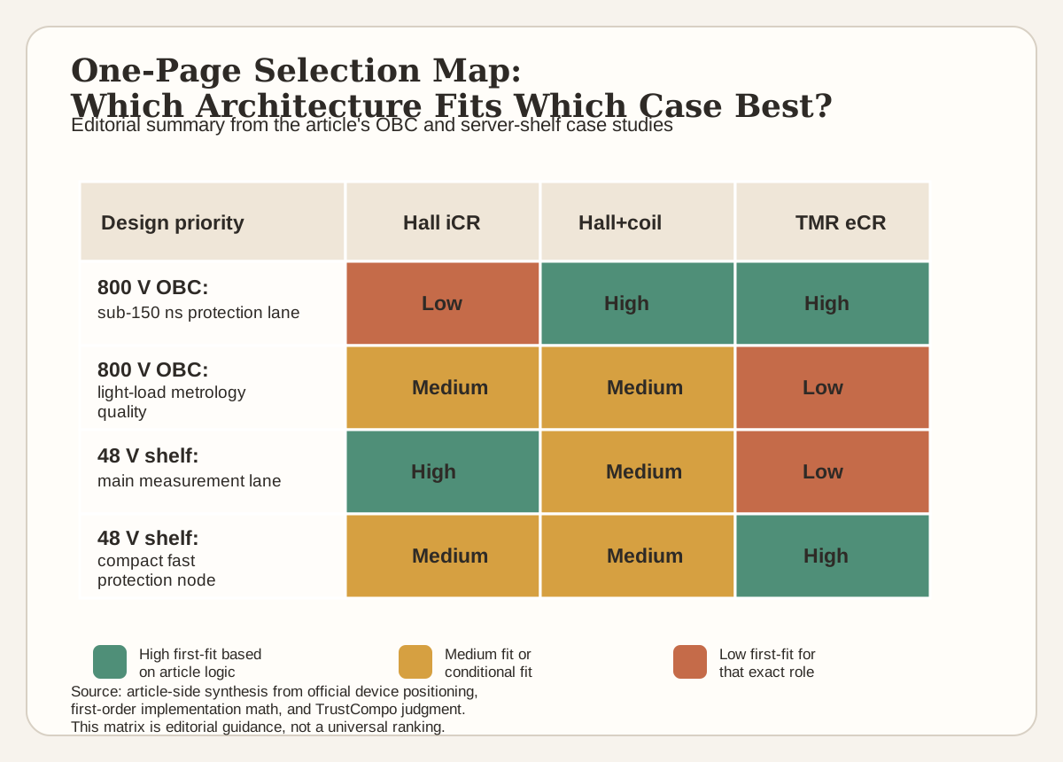
Step 1. Start from the fault path, not from the average current
The <=150 ns protection target immediately changes the baseline. Conventional Hall iCR is no longer the first lane to test, because the bottleneck is not just isolated measurement. It is protection speed under a fast-switching SiC environment.
That puts the first shortlist into:
- Hall+coil hybrid
- TMR eCR
Hall iCR can still remain on the long list for slower supervision paths, but it should not be the lead candidate for the main protection node.
Step 2. Compare large-step timing, not only bandwidth headlines
Now use the math from Section 3.1.
If a Hall+coil candidate advertises 9 MHz, the small-signal estimate is:
$$ t_{r_small} \approx \frac{0.35}{9 \text{ MHz}} \approx 39 \text{ ns} $$
But if the output path needs roughly 3 V of large-signal movement and the effective output-stage slew rate is around 30 V/us, then:
$$ t_ \approx 100 \text{ ns} $$
and the combined response estimate is:
$$ t_ \approx 107 \text{ ns} $$
That is still compatible with a <=150 ns protection budget, but only if the board does not waste the remaining margin on comparator delay, routing, or output conditioning.
This is the first real screening result:
- Hall+coil remains viable
- TMR eCR remains viable
- any slower Hall path should be pushed out of the main protection shortlist
Step 3. Check light-load control before declaring victory
Assume the controller still needs reliable current information around 1 A, and the candidate path has:
- sensitivity:
40 mV/A - offset drift over temperature:
+/-5 mV
Then the equivalent current bias is:
$$ I_{error_offset} = \frac{5 \text{ mV}}{40 \text{ mV/A}} = 125 \text{ mA} $$
Relative to a 1 A operating point, that is:
$$ 12.5% $$
At that point, the review question changes. The team is no longer asking only whether the sensor is fast enough. It is asking whether the same path can also support light-load control quality, or whether the architecture should split into:
- one fast protection path
- one slower but cleaner metrology path
That is often the hidden reason a single-sensor architecture fails review in high-end OBC designs.
Step 4. Compare geometry burden against package convenience
Suppose the TMR option uses an external conductor with an effective sensing distance of 1.0 mm, and the assembly stack-up can move by +/-0.1 mm.
The first-order gain spread is then about:
$$ \left| \frac{\Delta B}{B} \right| \approx \frac{\Delta z}{z} = 10% $$
That does not disqualify TMR. It simply means the program must honestly accept:
- conductor-geometry ownership
- assembled-board calibration
- tighter magnetic layout discipline
If the organization already has an EOL calibration station and thick-copper layout control, this can be acceptable. If it does not, Hall+coil may become the faster-to-release solution even if TMR looks cleaner in a concept slide.
Step 5. Account for the interface budget, not only the sensor budget
Now inspect the OCD routing.
If a designer adds even a seemingly tiny 1 kOhm by 100 pF RC filter to suppress switching spikes, the time constant is:
$$ \tau = 100 \text{ ns} $$
In a <=150 ns fault path, that single board-level choice can consume most of the remaining timing budget. The practical conclusion is that the chosen architecture must be reviewed together with:
- comparator delay
- pull-up value
- routing capacitance
- any deliberate or accidental RC filtering
Fast TMR and Hall+coil candidates often lose their "speed advantage" in practice here: not inside the silicon, but in the board interface.
Result of the worked example
For this 800 V OBC scenario, the shortlist usually converges to:
- First choice for a protection-first node: TMR eCR, if the program can support conductor control and EOL calibration
- Strong alternative when implementation risk matters more: Hall+coil hybrid, if the package and system isolation posture fit cleanly
- Secondary path for slower supervision or feedback lanes: Hall iCR, when the node is not carrying the hardest protection requirement
The key outcome is not that one technology always wins. It is that the workflow reveals where the real system cost lands:
- in timing budget
- in layout and mechanical tolerance
- in calibration flow
- in low-current control quality
That is what a useful shortlist should expose before layout freeze, not after it.
OBC summary table: inputs to shortlist outcome
Before leaving the OBC example, it helps to compress the reasoning into a single review snapshot:
| OBC review input | Engineering consequence | Shortlist effect |
|---|---|---|
SiC switching and <=150 ns protection target | conventional Hall iCR is too slow for the main protection lane | push Hall iCR out of the first protection shortlist |
| shunt loss already rejected | sensing path must stay low loss | favor Hall+coil or TMR over resistor-centric approaches |
| reinforced isolation posture | package and board geometry now matter, not just transfer specs | keep only architectures that fit the real HV boundary cleanly |
1 A light-load stability still matters | offset drift and zero-current behavior remain critical | question whether one fast path can also serve as the best metrology path |
| organization can or cannot support EOL calibration | determines whether eCR system accuracy is realistic | strong discriminator between TMR eCR and more package-controlled Hall lanes |
| board-level OCD filtering risk | timing margin can disappear outside the sensor die | fast candidates need full interface review, not only sensor approval |
The useful result is not "TMR wins" or "Hall wins." It is that the OBC team can see exactly which assumptions must stay true for each architecture to remain viable.
5.2 Worked example: narrowing the shortlist for a 48 V server power shelf
The OBC example is protection-heavy and isolation-heavy. A server or AI power shelf often shifts the center of gravity. The voltage is lower, but current density, thermal budget, and board area become brutal.
Assume a simplified 48 V to intermediate-bus power shelf stage with these requirements:
- switching technology: fast hard-switched GaN or SiC secondary stage
- main measured current:
+/-80 A - main concern: low sensing loss and current observability in a dense thermal environment
- protection target: fast fault containment is required, but
<=100 nsis not mandatory at every node - isolation: useful, but board-density pressure is now as important as high-voltage spacing
- production reality: the team can support calibration, but wants to minimize magnetic-layout surprises late in the program
This kind of design can easily tempt teams into overusing TMR simply because the power density is high. The right answer is more conditional than that.
Step 1. Start from power density and sensing loss
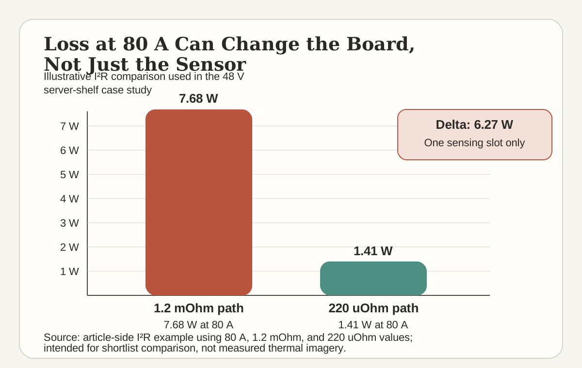
At 80 A, every sensing milliohm hurts. Even a simple first-order estimate shows why:
$$ P = I^2 R $$
For a 1.2 mOhm conduction path at 80 A:
$$ P = 80^2 \cdot 1.2 \text{ mOhm} = 7.68 \text{ W} $$
For a 220 uOhm path at the same current:
$$ P = 80^2 \cdot 220 \text{ uOhm} \approx 1.41 \text{ W} $$
That is already a difference of more than 6 W in one sensing position. In a dense server shelf, that is not a rounding error. It can change local copper temperature, airflow requirement, and heatsink allocation.
This immediately removes any casual attitude toward insertion resistance. A device that is merely "accurate enough" but thermally expensive may still be the wrong choice.
Step 2. Re-evaluate the role of Hall iCR
This is the kind of scenario where Hall iCR can remain more competitive than some engineers expect.
Why? Because the design is not driven only by absolute fastest shutdown. It is also driven by:
- manufacturable current-path control
- predictable thermal spreading
- simpler board integration
- lower chance of magnetic-layout surprises in a crowded shelf
So the shortlist behavior shifts:
- Hall iCR can remain viable for main measurement nodes if the bandwidth target stays in the low-
100s kHzclass - Hall+coil or TMR becomes more attractive only where waveform fidelity or faster fault observation is truly needed
In other words, not every high-density power shelf automatically wants TMR everywhere.
Step 3. Re-run the geometry penalty for compact TMR
Assume the team evaluates a compact TMR eCR path around an external conductor with the same 1.0 mm effective geometry reference used earlier.
If assembly and conductor placement still move by +/-0.1 mm, then the first-order gain spread remains around:
$$ 10% $$
In a server shelf, that spread may be acceptable for:
- fast protection thresholding
- trend observation
- branch current supervision
But it may be less attractive for:
- accurate current sharing between parallel phases
- tighter efficiency mapping
- telemetry that customers will compare across units
That is the point where some designs split the roles:
- Hall iCR for the cleaner main measurement lane
- TMR eCR or Hall+coil only where a faster protection or observability lane is justified
Step 4. Check whether the interface burden fits the shelf control architecture
Server shelves often centralize ADC resources and use tight digital control loops. That makes the ratiometric output rule from Section 3.7 more important, not less.
If the current sensor output is single-ended and ratiometric while the ADC reference comes from a separate precision rail, then supply ripple on the sensor rail can translate directly into false current movement. In a multi-rail shelf with noisy local bias networks, that can poison telemetry or current-sharing decisions even when the sensor core itself is performing properly.
This leads to a practical architecture question:
- does the shelf controller support a ratio-tracked reference strategy for the chosen sensor lane?
- or is a different sensor/output architecture easier to integrate cleanly?
That answer often matters more than one extra headline megahertz.
Result of the worked example
For a dense 48 V server or AI power shelf, the shortlist often converges differently than in the OBC case:
- First choice for dense but moderate-bandwidth measurement nodes: Hall iCR, when predictable current-path control and lower implementation risk matter more than absolute fastest edge visibility
- First choice for compact fast-protection or observability sub-nodes: TMR eCR, when low loss and compact isolated placement justify the geometry and calibration burden
- Strong hybrid option for high-speed measurement plus protection lanes: Hall+coil, when the design wants more dynamic visibility than Hall iCR can comfortably deliver but also wants to avoid the full geometry ownership of compact eCR
The same product family can look optimal in a white paper and suboptimal in a crowded shelf layout. The shortlist should follow the thermal map and control architecture, not only the sensor brochure.
Server-shelf summary table: inputs to shortlist outcome
| Server-shelf review input | Engineering consequence | Shortlist effect |
|---|---|---|
80 A class current in a dense shelf | insertion-loss watts become a board-level thermal problem | strongly penalize higher-resistance sensing paths |
protection is important, but not every node is <=100 ns critical | not every current lane needs the fastest architecture | keep Hall iCR alive for slower but cleaner measurement lanes |
| current sharing and telemetry quality matter | offset stability and repeatability remain important | question whether compact eCR is the best primary metrology lane |
| crowded magnetic environment | conductor routing and stray-field control get harder | favor package-controlled Hall where layout uncertainty is high |
| calibration is available but late surprises are expensive | geometry-dependent accuracy is acceptable only when the payoff is real | reserve TMR eCR for nodes that truly need its density or speed advantage |
Conclusion
The useful current-sensor question in 2026 is not "Hall or TMR?" in the abstract. It is: which magnetic architecture places the system burden in the most manageable place for your program?
That is the real dividing line behind the shortlist:
- If the burden should stay inside the package and the project values a robust, manufacturable isolated measurement path,
TLE4971-class Hall iCR devices still make strong sense. - If the burden should stay in a fast magnetic path without fully moving into external-conductor ownership,
TLE4978-class Hall+coil parts deserve serious attention. - If the program is willing to own conductor geometry, calibration flow, and tighter implementation discipline in exchange for faster protection and lower sensing-path burden,
TLE5571-class andTLI5572-class TMR parts become the more relevant starting points.
A good shortlist is never a beauty contest between bandwidth numbers. It is a decision about where the design team wants to pay: in conduction loss, in timing margin, in layout control, in calibration effort, or in low-current metrology performance.
If your team is still deciding whether the architecture should move away from shunt sensing at all, start with the companion article on the system-level Hall-versus-TMR tradeoff. If the architecture call is already made and the next step is a release-grade shortlist, this framework is the more useful place to begin.