- current sensing
- Hall sensor
- TMR sensor
- power conversion
Shunt vs Hall vs TMR Current Sensing: System-Level Comparison for Power Conversion
Compare shunt, Hall, Hall+coil, and TMR current sensing for power conversion across loss, isolation, bandwidth, protection speed, layout burden, and total solution cost.
Quick facts
- A shunt still wins many low-cost measurement jobs, but it always puts resistance and heat directly in the measured current path.
- As of August 25, 2026, Infineon officially positions Hall-based TLx497x and TMR-based TLx557x current sensors as complementary technologies rather than universal replacements for one another.
- The practical split is no longer just shunt versus Hall. It is shunt, Hall with an integrated rail, Hall+coil hybrid sensing, or TMR near an external conductor.
- Magnetic current sensing does not mean zero loss. It usually means much lower sensing-path resistance than a dedicated shunt, while moving design burden into conductor geometry, shielding, and validation.
- TMR earns attention when protection latency, bandwidth, and lower insertion loss matter more than the simplicity of a resistor plus amplifier.
For power conversion, the practical comparison is shunt vs Hall vs TMR current sensing, not a general Hall-effect vs AMR vs TMR position-sensor debate. Shunts measure current through resistance. Hall current sensors measure the magnetic field around a package-controlled or conductor-defined current path. TMR current sensors usually move toward a compact external-conductor magnetic pickup with high bandwidth and fast protection behavior.
The short answer: choose a shunt when cost, simplicity, and precision measurement matter more than heat or isolation; choose Hall with an integrated current rail when the design needs mature isolated current measurement with lower layout burden; choose Hall+coil or TMR when fast switching, low insertion loss, compact placement, or sub-200 ns class protection starts to dominate the system decision.
In 2026, the practical current-sensing question is no longer only "shunt or magnetic?" It is which sensing architecture preserves the most system margin once loss, heat, isolation, bandwidth, and fault response time are all counted together.
That is why shunt resistors are losing ground in part of the market. A shunt is still simple, inexpensive, and easy to model. But it also inserts deliberate resistance into the measured path, creates heat where current is highest, and often pushes the isolation or amplifier problem elsewhere in the design. In OBCs, DC-DC stages, inverters, e-fuses, server power, and high-density motor drives, those tradeoffs stop being small.
Magnetic current sensing is the next shortlist for many teams, but "Hall versus TMR" is still too broad. Recent official product material from Infineon and Allegro points to at least four real lanes:
- shunt plus amplifier
- Hall with an integrated current rail
- Hall+coil hybrid sensing for much higher bandwidth
- TMR near an external conductor for compact isolated sensing and fast protection
This article follows that system split. It does not treat TMR as a universal Hall replacement or magnetic sensing as a universal shunt replacement. The goal is simpler: show where each architecture moves system cost, implementation effort, and design risk.
Quick Comparison: Which Current-Sensing Architecture Fits First?
| Architecture | Best first fit | Main advantage | Main approval risk |
|---|---|---|---|
| Shunt plus amplifier | low-cost, low-side, precision-friendly current measurement | direct, familiar, easy to model | insertion loss, heat, isolation or common-mode amplifier burden |
| Hall with integrated current rail | isolated AC/DC current measurement with lower implementation burden | package-controlled current path and mature behavior | moderate bandwidth and package current-path limits |
| Hall+coil hybrid | fast isolated current observation in SiC, GaN, OBC, and DC-DC stages | MHz-class bandwidth with fast OCD from a Hall-derived architecture | package, interface, and availability review still matter |
| TMR near an external conductor | compact high-current sensing, low-loss protection, e-fuse, battery, server-power, and dense converter nodes | low insertion burden, compact placement, fast response | conductor geometry, calibration, stray-field control, and overload validation |
This is also why current-sensing content should not be judged against Hall/AMR/TMR position detection guides as if the intent were identical. Position-sensor comparisons focus on magnet angle, air gap, angular accuracy, encoder behavior, and AMR periodicity. Current-sensor comparisons focus on insertion resistance, isolation, copper temperature, bandwidth, overcurrent reaction, conductor geometry, and fault behavior.
Architectural Baseline
Scope note: this comparison is built primarily from official Infineon and Allegro product pages, technology notes, and application material reviewed on August 25, 2026. The part-level facts below come from those sources. The system-level conclusions are engineering interpretation rather than a single shared bench comparison under one converter setup.
| Source basis reviewed through August 25, 2026 | What it supports | How this article uses it |
|---|---|---|
| Infineon current-sensor overview | Official Hall TLx497x versus TMR TLx557x portfolio framing, iCR versus eCR architecture split, and application lanes such as OBC, EV charging, industrial drives, and PV inverter | Establishes that Hall and TMR are complementary lanes, not one single migration path |
Infineon TLE4978-R050W5-O-S0010 product page and March 16, 2026 technology news | 9 MHz bandwidth, 100 ns OCD, reinforced isolation, hybrid Hall+coil architecture | Supports the point that the Hall lane now includes much faster architectures than older Hall assumptions imply |
Infineon TLE4971-A050N5-E0002 product page | 220 µOhm integrated rail, typical 210 kHz bandwidth, dual OCD outputs, stray-field suppression | Provides a mature Hall iCR anchor below 100 A |
Infineon TLE5571-AE24O5-I-S0001 and TLI5572 product pages | TMR eCR architecture, >2.5 MHz or >1 MHz bandwidth, sub-150 ns or 140 ns response, compact placement, shunt-replacement messaging | Supports the protection-first and compact isolated sensing arguments for TMR |
Allegro ACS724 and ACS758 product pages plus ACS724 field-interference note | Differential Hall sensing, integrated shielding, low conductor resistance, 120 kHz bandwidth, layout caveats | Shows why Hall remains competitive when integrated conductor geometry and mature isolated sensing matter |
Why the Shunt Is No Longer a Neutral Default
A shunt resistor looks electrically honest because it measures current directly. That is still true, and it is why shunts remain strong in many low-cost and low-side designs. But the resistor is not free. It adds three system penalties:
- insertion loss in the measured path
- heat generation in the same path
- a second design problem around isolation, common-mode range, or amplifier accuracy
At light power, those penalties may be manageable. At higher current, they can reshape the entire architecture. A resistor that looks small on the schematic becomes:
- efficiency loss in an OBC or server PSU
- extra thermal rise inside a sealed drive
- more copper and cooling burden in a battery or bus converter
- a harder isolation problem if the measurement point is high-side
That is the practical reason shunts lose ground. It is not because the shunt suddenly stopped working. It is because modern power systems are less willing to spend thermal and isolation budget in the sensing element.
In real design reviews, this is usually the moment when the "cheap and familiar" shunt stops looking cheap. The resistor itself may still be inexpensive, but the surrounding cost starts to show up elsewhere: copper width, thermal margin, isolation circuitry, fault qualification, and sometimes a last-minute efficiency problem that no one wanted the sensing path to create.
What the Shunt Still Does Better
This article should not be read as a verdict against shunts. In several cases, the shunt is still the better engineering choice:
- when the current loop does not require galvanic isolation
- when the bandwidth target is achievable with the chosen resistor, amplifier, and layout
- when the system can tolerate the dissipation
- when cost, familiarity, and debug simplicity matter more than the efficiency penalty
- when the measurement job is more about steady-state control or metering than ultra-fast fault handling
That last point matters. Some magnetic sensors are especially strong as protection elements, while a shunt-based path may still remain attractive for precision measurement or controller feedback in the same system. The real design question is not whether the shunt is obsolete. It is whether the shunt should keep carrying the primary burden in this stage.
That split is one of the most common places teams get unstuck. Once the discussion changes from "one sensor must do everything" to "measurement path and protection path may deserve different architectures," the shortlist usually becomes much clearer.
Hall Does Not Remove Complexity. It Relocates It.
Hall current sensing became attractive because it can reduce the direct resistive burden of the sensing path and give the designer an isolated magnetic measurement path. That is a powerful architectural change. It can reduce insertion loss compared with a dedicated shunt, simplify high-side isolation, and make the analog front end less exposed to large common-mode swings.
But Hall does not make complexity disappear. It relocates complexity into:
- conductor geometry
- magnetic coupling quality
- package and shielding behavior
- layout sensitivity to stray fields and dv/dt stress
Hall current sensors are strongest when the package already controls a large part of the geometry problem. Official examples reviewed on August 25, 2026 make that clear:
- Infineon's TLE4971A050N5E0002XUMA1 integrates a current rail with 220 µOhm insertion resistance and typical 210 kHz bandwidth.
- Allegro's ACS724LLCTR-20AB-T uses differential Hall sensing, an integrated shield, and a 1.2 mOhm primary conductor with 120 kHz bandwidth.
- Allegro's ACS758LCB-050B-PFF-T keeps conductor resistance down to 100 µOhm while preserving galvanic isolation and 120 kHz bandwidth.
These are system advantages, not abstract physics talking points:
- lower sensing-path loss than a typical dedicated shunt solution at comparable current
- easier high-side measurement
- cleaner isolation posture
- a more turnkey conductor-to-sensor relationship than an external magnetic pickup
The tradeoff is that the package and its current path become part of the measurement architecture. You are no longer choosing only a sensor IC. You are choosing a conductor implementation as well.
That distinction matters in practice. Teams often evaluate integrated-rail Hall parts successfully on the first pass because the package already fixes much of the magnetic geometry. The review burden is still real, but it is usually more predictable than with an external-conductor architecture that depends on PCB copper shape, spacing, and local mechanical tolerances.
Bandwidth alone is not enough in high-dv/dt power stages
In SiC and GaN converters, raw bandwidth is only part of the story. Fast-switching nodes can move at tens of volts per nanosecond, and aggressive designs can push well beyond that. In that environment, the more practical question is not only "can the sensor see the waveform?" but also "can it stay quiet while the power stage is slewing hard?"
The failure mechanism is straightforward. Any isolated magnetic sensor package has some parasitic capacitance between the high-energy current path and the low-voltage signal chain. When the primary node slews quickly, displacement current can couple into the analog front end or local ground reference and create output spikes, false OCD events, or brief recovery distortion. That is why shielding technology matters. Allegro's ACS724 family explicitly highlights an integrated shield that suppresses output noise from high dv/dt transients, while Infineon's TLE4971 family is positioned as robust against voltage slew rates up to 10 V/ns and as stray-field-robust through its differential principle.
This is also where the shunt path remains more competitive than headline chip prices suggest. A shunt plus isolated amplifier or sigma-delta modulator still has to survive the same switching environment, but devices such as TI's AMC1300 family publish an explicit CMTI specification, with the AMC1300B variant called out at 100 kV/µs minimum on TI's product page. That gives the engineer a clean isolation-barrier number to design around, even though the total solution still has to manage noise from the floating high-side supply and the rest of the isolation power chain.
Hall Is Now Two Different Lanes
One reason public discussions become muddy is that "Hall current sensor" now covers devices with very different system behavior.
1. Integrated-rail Hall devices
This is the mature lane represented by parts such as TLE4971A050N5E0002XUMA1, ACS724LLCTR-20AB-T, and ACS758LCB-050B-PFF-T. These devices are strong when the design wants:
- integrated galvanic isolation
- a known current path inside the package
- lower insertion loss without external magnetic design
- moderate control bandwidth with clean AC/DC measurement
- a measurement path that is easier to package than a custom external busbar sensor
2. Hall+coil hybrids
Infineon's TLE4978R050W5OS0010XUMA1 matters because it breaks the old assumption that Hall automatically means modest bandwidth. Infineon's March 16, 2026 technology note describes the part as a hybrid Hall+coil architecture where Hall elements handle the low-frequency portion and coil elements capture fast-changing current. The official result is a 9 MHz bandwidth current sensor with 100 ns overcurrent detection.
That matters for system design because it changes what the magnetic lane can observe:
- faster switching edges
- richer current waveform detail
- shorter protection latency
- better fit with SiC and GaN stages where current transitions are much faster than older silicon power platforms
Once Hall includes hybrid Hall+coil implementations, the old "Hall is slow, TMR is fast" framing stops being useful. The real question becomes which magnetic architecture gives enough bandwidth and protection speed without adding the wrong kind of package or current-path burden.
That is where older mental models usually fail. Engineers who last reviewed Hall sensing a few product generations ago often still associate it with moderate bandwidth and metering-oriented use. For fast power stages in 2026, that assumption is no longer safe.
Where TMR Changes the Equation
TMR earns attention because it shifts the design toward a compact magnetic pickup around an external conductor instead of an integrated current rail or a dissipative resistor. Official Infineon positioning on August 25, 2026 is explicit here: the TLx557x family is the TMR lane for high bandwidth, fast response, high SNR, and low power. In practical shortlist work, TLE5571AE24O5IS0001XUMA1 and TLI5572AE15E1E0001XTSA1 are useful anchors because they make the protection-first eCR case concrete, while TLE4978R050W5OS0010XUMA1 is the reminder that some Hall-derived architectures now reach similar speed classes from a different implementation path.
The bandwidth split is easier to grasp visually than in paragraph form. The chart below stays intentionally narrow: it compares the official headline bandwidth values published for the representative anchor parts reviewed on August 25, 2026, without implying a one-to-one bench comparison.
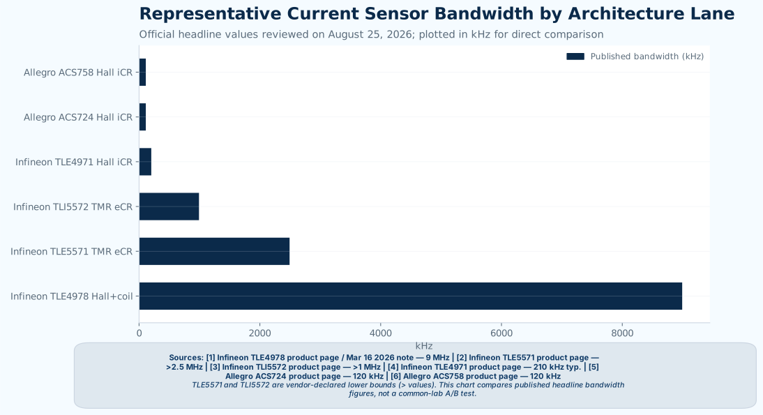
These anchor parts are used here as architecture examples, not as a same-class approved AVL. The point of the chart is to show how far the bandwidth lanes separate once Hall iCR, Hall+coil, and TMR eCR are treated as different implementation choices.
TMR becomes compelling when the system priority is one or more of the following:
- fast overcurrent shutdown
- MHz-class current observation
- compact isolated placement near a busbar or copper path
- minimizing sensing-path loss without sacrificing protection speed
In review meetings, TMR usually earns approval fastest when the problem is framed as a protection problem first and a measurement problem second. The weakest TMR justifications are usually the ones that start with "it can replace a shunt everywhere." The strongest ones start with "this stage needs faster fault action, lower insertion loss, or less thermal burden than the shunt path is giving us."
But TMR does not come as a free win. It introduces its own approval work:
- external conductor placement must be controlled
- magnetic field strength at the sensing point must be understood
- the mechanical stackup becomes part of the current measurement function
- the system still has to validate drift, fault thresholds, and interference behavior
In practice, two implementation costs matter more than many top-level comparisons admit.
1. Magnetic-path tolerance and calibration cost
Infineon's official eCR current-sensor overview explicitly says that external-current-rail devices measure the field from an external conductor such as PCB copper traces or busbars and provide accurate measurements after a one-time end-of-line calibration following assembly. That detail matters because an eCR TMR design is not defined by the sensor IC alone. It is defined by:
- conductor width and thickness
- sensor-to-conductor spacing
- mounting orientation
- local air gap or slot geometry
- production tolerance from board or busbar assembly
That makes the signal-transfer factor partly a mechanical and layout problem, not just a silicon problem. A shunt-based path usually gets its primary gain-setting element from resistor value and resistor tolerance. An eCR TMR path usually needs tighter control of the magnetic path, and in many implementations that pushes work into end-of-line calibration, firmware compensation, or both.
This is one of the most common underestimates in early architecture comparisons. On a whiteboard, eCR TMR looks cleaner because the resistor loss disappears. On a production line, the work often reappears as fixture definition, calibration flow, tolerance management, and firmware ownership.
Stray-field immunity is the other gating variable
A shunt is naturally insensitive to external magnetic fields. An eCR magnetic sensor is not. In dense inverter, charger, and busbar layouts, the sensor is trying to measure a local magnetic field while sitting next to other current-carrying conductors, inductors, and high-energy switching loops. That makes stray-field rejection a first-order design requirement rather than a nice-to-have feature.
This is why differential sensing matters so much. Infineon positions its Hall current sensors as robust against external homogeneous fields, and the TLE4971 family explicitly ties its stray-field suppression to a differential measurement principle. Allegro makes a similar point on ACS724, where differential Hall sensing is described as rejecting common-mode fields in magnetically noisy environments. The same logic applies to eCR TMR layouts: two spatially separated sensing points can reject much of the common external field if both points see nearly the same interference field, while still resolving the intended field gradient from the measured conductor.
The catch is layout realism. That common-mode rejection only holds when the stray field is reasonably uniform across the sensing points. In crowded busbar or thick-copper layouts, eccentric routing, copper asymmetry, via placement, or nearby phase conductors can distort the field enough to turn a good differential concept into a calibration problem. In the worst environments, designers may still need additional magnetic shielding or tighter mechanical control, which can quickly erode the packaging and cost advantage that made the eCR path attractive in the first place.
2. Temperature drift and compensation burden
Temperature behavior is another place where the architectures carry different costs. Infineon's TLI5572 product page says its quoted 3% accuracy over temperature is achieved after end-of-line calibration. That is useful, but it also reinforces the system point: magnetic sensing accuracy over temperature is part of the full implementation, not only the sensor die.
By contrast, low-value metal-strip shunts are often sold precisely on low TCR behavior. Vishay's WSLF current-sense resistor family advertises low TCR (< 20 ppm/°C), and Vishay's battery-shunt portfolio includes parts described as low TCR down to < ± 10 ppm/°C. That does not mean a shunt path is automatically better overall, because the shunt still burns power and raises local temperature. It does mean the thermal error budget is often easier to model from resistor characteristics alone than from an external magnetic path plus sensor plus compensation chain.
For that reason, teams that are comfortable with resistor-based error budgets sometimes underestimate how much organizational change a magnetic path introduces. The challenge is not only offset drift. It is who owns compensation, who signs off calibration, and who has to explain production spread when the current path is partly a mechanical structure.
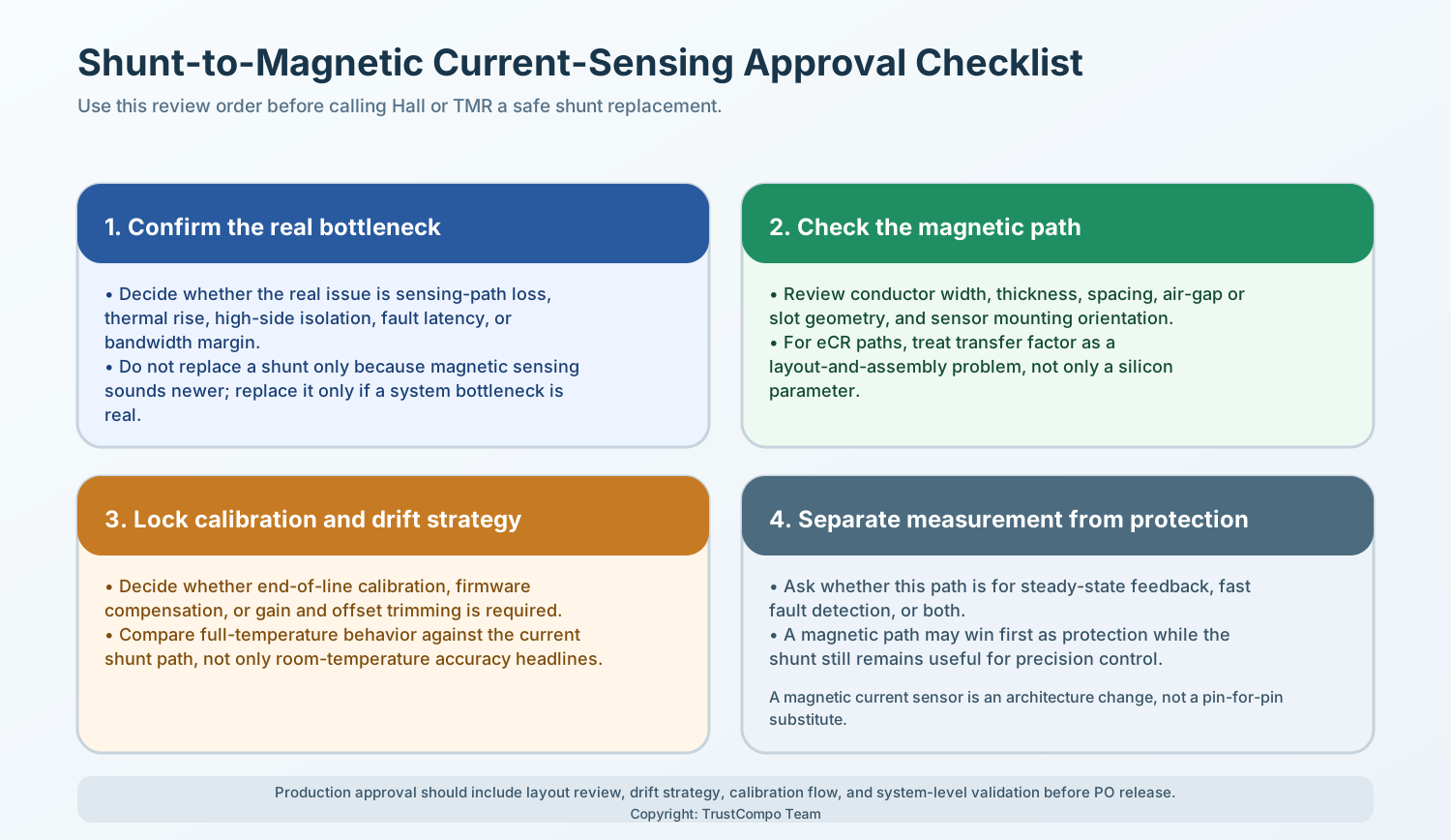
That is the main caution point: TMR can replace a shunt in some designs, but it does not remove the need for architecture-level validation. It is usually easiest to justify first in fault-detection paths, not as a universal substitute for every precision-feedback path.
The Real Comparison Is Not Sensor Physics. It Is System Burden.
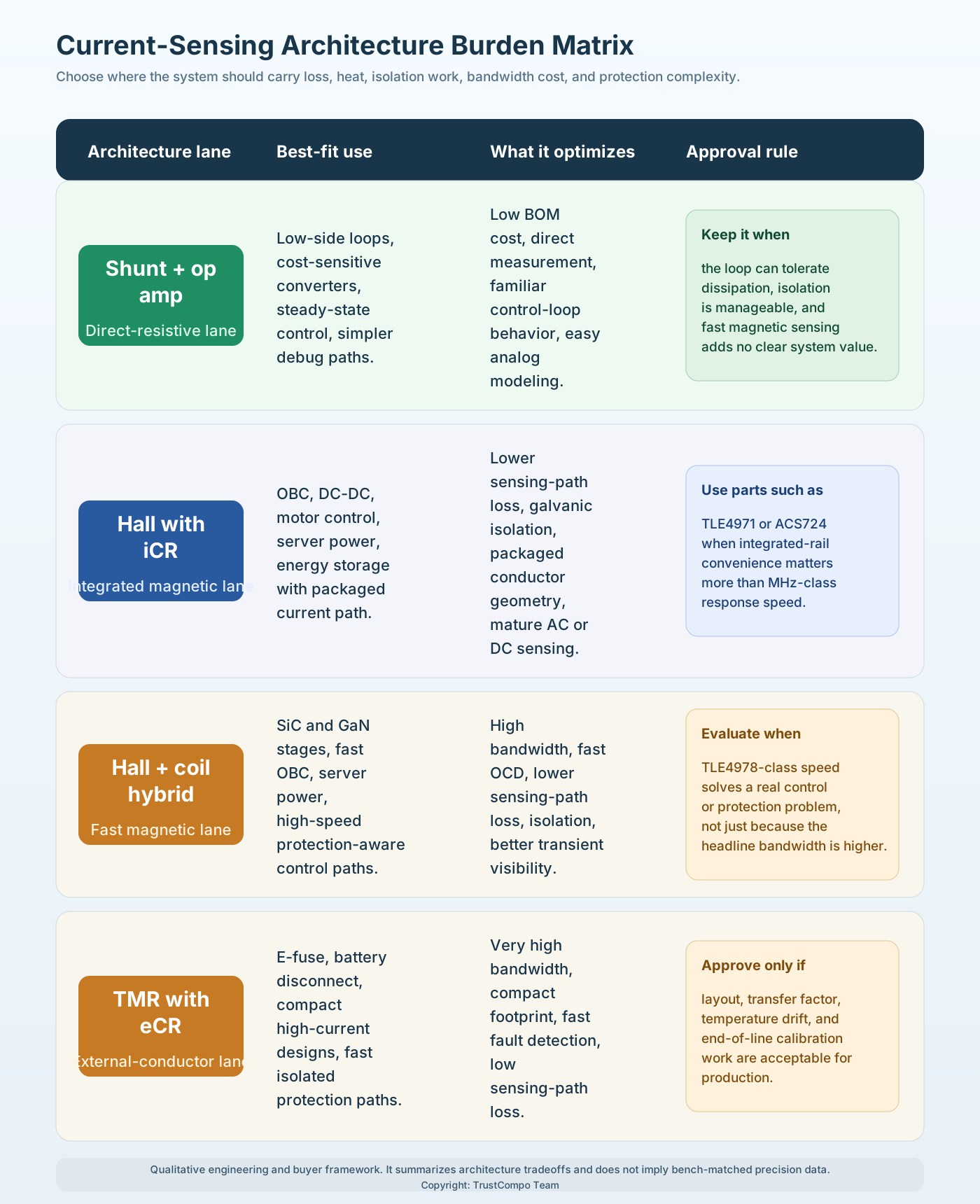
The quickest way to keep this topic useful is to compare what each sensing architecture burdens the system with.
| Architecture | What it does well | What it burdens | Best-fit use cases | Typical approval question |
|---|---|---|---|---|
| Shunt plus amplifier | Low cost, direct measurement, familiar control behavior, strong fit for steady-state measurement paths | insertion loss, heat, common-mode and isolation design, amplifier error chain | low-side current loops, cost-sensitive converters, moderate current stages | Can we afford the loss and thermal rise where we measure? |
| Hall with integrated current rail | Isolated measurement, lower insertion loss, packaged conductor geometry, mature AC/DC sensing | package current path limits, magnetic layout discipline, moderate bandwidth ceiling in many families | OBC, DC-DC, motor control, energy storage, server power below or around the integrated-rail sweet spot | Is the integrated current path and bandwidth enough for this loop? |
| Hall+coil hybrid | Higher bandwidth while staying in the magnetic lane, fast OCD, good fit for fast-switching power stages | more device-specific architecture, premium positioning, still package-dependent | SiC and GaN power conversion, fast protection stages, advanced OBC or server power | Do we need this bandwidth, or are we paying for speed we will not use? |
| TMR with external conductor | very high bandwidth, compact isolated placement, low sensing-path loss, strong protection potential | conductor geometry design, field-coupling sensitivity, validation burden, architecture tuning | e-fuses, battery disconnect, high-density power stages, compact high-current systems | Can we control the external magnetic path tightly enough for production? |
For engineering and sourcing teams, this view is usually more actionable than a generic Hall-versus-TMR ranking because it shows where the design is really paying for the decision.
Total Solution Cost Usually Turns at the Isolation Boundary
The most common sourcing mistake in this topic is to compare one shunt resistor price against one magnetic-sensor price. The real decision is a system-BOM decision, and the balance point usually moves when isolation, heat, and calibration work are included.
| Solution path | What usually sits in the BOM | Where the hidden cost shows up | Typical economic posture |
|---|---|---|---|
| Shunt plus amplifier on a non-isolated low-side path | shunt, amplifier, filtering, precision routing | thermal rise and error budgeting stay manageable if current is modest | Usually still the lowest-cost path below roughly the high-tens-of-amps range when isolation is not required |
| Shunt plus isolated amplifier or modulator | shunt, isolated amplifier or modulator, biasing, filtering, and often isolated power support | isolation BOM, creepage/clearance constraints, small-signal noise handling, and concentrated I²R heat | Often becomes less attractive once current is high enough that thermal design and isolation support start dominating the bill of materials |
| Integrated-rail Hall or Hall+coil | one isolated magnetic sensor plus light support circuitry | package selection, bandwidth fit, and system qualification rather than large analog support BOM | Often reaches cost parity surprisingly quickly in isolated >50 A designs because insertion loss and support circuitry shrink together |
| eCR TMR | compact sensor IC with minimal analog support around a designed conductor path | EOL calibration, fixtures, tolerance control, firmware compensation, and sometimes shielding | Can look cheapest on schematic, but the production flow determines whether it stays cheap |
At 100 A, even a 500 µΩ shunt burns about 5 W, which is often no longer a "small sensing loss." Once the design also needs reinforced isolation, an isolated front end, or a digital isolator path, the total solution cost can swing much faster than the single-component view suggests. That is usually the point where integrated magnetic sensors stop looking like premium parts and start looking like system simplifiers.
Application Matrix: Where Each Architecture Fits
Different power stages fail for different reasons, so the right sensing architecture changes by application.
| Application lane | What matters most | Best starting candidates | Why |
|---|---|---|---|
| On-board charger | efficiency, galvanic isolation, fast fault reaction, temperature rise | Hall iCR, Hall+coil hybrid, TMR protection path | OBC stages punish extra loss and often need strong isolation plus fast fault response |
| HV or isolated DC-DC converter | bandwidth, transient visibility, compact layout, dv/dt robustness | Hall+coil hybrid, TMR, ACS724-class Hall if bandwidth is enough | Fast-switching stages expose the limits of low-bandwidth sensing quickly |
| General-purpose motor drive | robust AC/DC measurement, fault detection, cost discipline | Hall iCR, ACS724-class Hall, shunt where isolation is not severe | Many drives still do not need TMR-class speed if the loop and power stage are moderate, especially when a shunt can stay low-side |
| E-fuse or battery disconnect | ultra-fast overcurrent response, compact placement, low loss | TLE5571-class TMR, TLI5572-class TMR | Protection latency matters more than long-window metrology |
| Server power and AI power shelves | efficiency, density, fast switching, manageable thermal load | Hall+coil hybrid, TMR, selected Hall iCR | The sensing path must keep up with denser and faster stages without adding avoidable heat |
| Power tools, drones, compact high-current platforms | space, heat, isolated measurement, low BOM sprawl | TLI5572-class TMR, selected Hall solutions | Small footprints and high peak current make shunt heat and amplifier overhead less attractive |
If the application matrix above already makes the architecture call clear, the next step is not another system-level comparison. It is a parameter-priority pass across bandwidth, insertion loss, geometry control, calibration method, and stray-field behavior. That next layer is covered in How to Choose Hall or TMR Current Sensors for Power Conversion: A Datasheet-First Framework.
Conclusion
Shunt resistors are losing ground because modern power systems are less willing to spend voltage drop, heat, and isolation budget inside the sensing element. That does not make the shunt obsolete. It means the shunt is no longer the default answer once power density, isolation, or protection latency becomes tight.
Hall remains the strongest next step when the design wants an integrated and mature isolated current path, especially in packages that already control conductor geometry. TMR becomes more convincing when the design wants compact placement, very high bandwidth, and very fast protection around an external conductor. Hybrid Hall+coil parts matter because they show that the Hall lane itself now reaches much further into fast power-conversion territory than many engineers still assume.
The most reliable shortlist does not start with "Hall or TMR?" It starts with "which path is doing precision measurement, which path is doing fast protection, and where can this system afford loss, heat, isolation complexity, and protection delay?" That framing usually removes three common mistakes early: assuming TMR is always more accurate than Hall, assuming Hall is always too slow for modern power conversion, or treating a magnetic sensor as a shunt replacement without rechecking layout and validation.
Sourcing Next Step
If this article is feeding an actual OBC, DC-DC, inverter, e-fuse, or server-power review, the most useful next step is to build the shortlist by architecture lane instead of by marketing label: shunt baseline, integrated-rail Hall, fast Hall+coil, and protection-first TMR. That usually gives engineering and sourcing teams a cleaner way to align electrical priorities, package limits, and qualification effort before the decision hardens into a late-stage redesign.