

CD4097BE Interface - Analog Switches, Multiplexers, Demultiplexers by Texas Instruments
CD4097BE is a Interface - Analog Switches, Multiplexers, Demultiplexers from Texas Instruments in DIP packaging. It is commonly reviewed for IC MUX/DEMUX DUAL 1X8 24DIP. This page lists current TrustCompo stock, tier pricing, package data, datasheet access, compliance attributes, Hong Kong warehouse shipping options, payment confirmation, and RFQ options for buyers verifying this exact ordering code.
Pictures are for reference only. Please contact us for the latest pictures.

- 365-Day GuaranteeAfter-sales support helps buyers handle quality questions with a clearer return and review window.
- Ships within 24-48 HoursAvailable items can move quickly once the quote, quantity, and delivery details are confirmed.
- 100% Anti-Counterfeit TestedParts are checked through authenticity-focused handling and inspection before shipment.
Key specifications
- Part Number
CD4097BE
- Internal code
TCE000110086
- Package
DIP
- Manufacturer
- Texas Instruments
Key specifications
- Series
-
- Min Quantity
1
- Category
- Integrated Circuits (ICs)
- Description
IC MUX/DEMUX DUAL 1X8 24DIP
- key Attributes
-
Trust signals
Quality and trust signals
Review TrustCompo quality credentials, traceability support, anti-counterfeit handling, and inspection controls before sending an RFQ.
4 certifications
ISO 9001
Quality management processes for more consistent sourcing and handling.
AS9120B
Aerospace-focused distribution controls for traceability and reliability.
ISO 14001
Environmental management discipline across warehouse and operating workflows.
ESD Control
Electrostatic handling standards to help protect sensitive components.
RFQ checklist
Order process
Confirm the core buying details for CD4097BE before RFQ, PO release, and shipment planning.
- 1
Confirm MPN
Use the exact part number, manufacturer, package, and approval constraints in the RFQ.
- 2
Check stock and price
Verify live availability, MOQ, lead time, final unit price, and tax terms before PO release.
- 3
Align documents
Confirm datasheet, CoC, traceability, lifecycle notes, and inspection scope when required.
- 4
Arrange shipment
Release the PO and align DHL, FedEx, UPS, or buyer forwarder shipment from Hong Kong.
Before PO release
Part confirmation
- Exact MPN confirmed: CD4097BE
- Package to verify: DIP
Commercial confirmation
- Live stock and lead time confirmed by RFQ
- Final price and tax terms confirmed before PO release
Fulfillment & documents
- Ship-from location: Hong Kong warehouse
- Shipping method: DHL, FedEx, UPS, or buyer forwarder account
Product overview
Product overview
Review the sourcing context for CD4097BE from Texas Instruments, including product identity, application fit, package notes, and purchasing considerations.
The CD4071BC and CD4081BC quad gates are monolithic complementary MOS (CMOS) integrated circuits constructed with N- and P-channel enhancement mode transistors.
They have equal source and sink current capabilities and conform to standard B series output drive.
The devices also have buffered outputs which improve transfer characteristics by providing very high gain.All inputs protected against static discharge with diodes to VDD and VSS.
Features
• Low power TTL compatibility: Fan out of 2 driving 74L or 1 driving 74LS
• 5V–10V–15V parametric ratings
• Symmetrical output characteristics
• Maximum input leakage 1 µA at 15V over full temperature range
Technical parameters
Parameters
Compare grouped CD4097BE parameters from Texas Instruments, including package, series, key attributes, and technical values used for engineering and sourcing review.
Product Attribute
Categories
Integrated Circuits (ICs)
Product Attribute
Manufacturer
Texas
Product Attribute
Sub-Categories
Interface - Analog Switches, Multiplexers, Demultiplexers
Product Attribute
Housing Material
ROHS3 Compliant
Product Attribute
Number Of Contacts
No SVHC
Product Attribute
Locking Feature
Lead Free
| Parameter | Value |
|---|---|
Categories Lists the product categories or classifications assigned to this component, such as connectors, capacitors, or modules. This helps in filtering and comparing similar parts. Review the categories to ensure the component fits your application and to find alternative parts in the same class. | Integrated Circuits (ICs) |
Manufacturer Identifies the company that designed and produced the component. Buyers often filter by manufacturer to ensure brand reliability, quality standards, and supply chain consistency. Verify the manufacturer against the datasheet and official packaging to avoid counterfeit parts. | Texas |
Sub-Categories Indicates the specific product subcategories or classifications within the broader component family. Helps narrow down search results and identify the exact type of component needed for your design. Review the subcategory to ensure compatibility with your application. | Interface - Analog Switches, Multiplexers, Demultiplexers |
Housing Material Specifies the material of the component's outer casing, such as plastic, metal, or ceramic. This affects durability, thermal performance, and environmental resistance. Verify against datasheet for application-specific requirements like flammability or chemical exposure. | ROHS3 Compliant |
Number Of Contacts Total number of electrical contacts in the connector, which determines the maximum number of circuits that can be connected. This is a critical parameter for matching the connector to your wire harness requirements. Ensure the contact count aligns with your signal and power needs. | No SVHC |
Locking Feature Indicates the locking mechanism used to secure the connector or terminal in place. Choose the appropriate type for your application to ensure reliable mating and vibration resistance. Verify compatibility with the mating part and datasheet specifications. | Lead Free |
Number Of Bits Bit width of digital data processed by a converter, processor, or memory. Higher bits mean better resolution or precision. Verify against datasheet to match your system's data width and accuracy needs. | No |
Driver Number Of Bits Specifies the number of bits the driver can handle, indicating the width of the data path or the number of channels. This determines the maximum data throughput and the number of outputs. Ensure it matches your system's bus width or channel requirements. | Gold |
Converter Type Identifies the conversion architecture, such as ADC, DAC, or DC-DC. This determines the signal path, interface, and performance characteristics. Verify the type matches your system's analog or digital conversion needs before selecting the part. | 1 (Unlimited) |
Mounting Feature Describes special mechanical characteristics for mounting, such as through-hole, surface mount, or specific clips. Ensures compatibility with your PCB layout and assembly process. Confirm before designing the footprint. | Non-Inverting |
Tolerance Allowed deviation from the nominal value, expressed as a percentage. Determines precision of resistors, capacitors, and inductors. Choose tighter tolerance for precision circuits, but verify actual performance in the datasheet. | 1 |
Radiation Hardening Indicates if the component is designed to withstand ionizing radiation in space, nuclear, or high-energy physics applications. Compare radiation-tolerant vs. radiation-hardened parts for mission-critical designs. Verify the total ionizing dose (TID) and single-event effect (SEE) ratings in the datasheet. | -55°C~125°C TA |
Package / Case Physical package or case type of the component, defining its dimensions, mounting style, and thermal characteristics. Common types include SMD, through-hole, BGA, and QFN. Choose the package that fits your PCB layout and assembly process. Verify the exact package code in the datasheet for footprint compatibility. | 24-DIP (0.600, 15.24mm) |
Terminal Position Position of the terminals on the package, such as dual-in-line, gull-wing, or J-lead. This affects PCB layout, soldering, and thermal performance. Engineers must ensure the terminal position matches the footprint and assembly capabilities of their manufacturing line. | Through Hole |
Max Supply Voltage Indicates the highest DC or AC voltage that can be safely applied to the power supply pin without risking damage or malfunction. Verify this limit against the datasheet before designing your circuit to ensure reliable operation under all conditions. | Through Hole |
Contact Material Specifies the metal alloy used for the electrical contact surfaces, affecting conductivity, wear resistance, and corrosion behavior. Compare materials like silver, gold, or palladium for signal integrity and durability. Verify against datasheet for application-specific requirements. | 2 |
Data Rate Specifies the maximum data transfer rate the component can handle, typically in bits per second. Compare this value with your system's required throughput to ensure adequate bandwidth. Verify against the datasheet for exact conditions and supported protocols. | 24 |
Temperature Grade Defines the operating temperature range classification for the component, such as commercial, industrial, or automotive. This indicates the environmental conditions the device can withstand. Ensure the grade matches your application's ambient temperature requirements. | 24 |
Turn On Time Time required for the device to transition from off state to fully on state. This parameter is critical for timing analysis in power supplies, drivers, and switching circuits. Verify this value against your system's timing budget and switching frequency requirements. | 3V |
Voltage Indicates the maximum voltage the component can withstand or operate at, depending on context. Critical for ensuring the part is not overstressed in your application. Always compare with your circuit's voltage levels and consider transient spikes. | 500mW |
Minimum Operating Temperature Specifies the lowest ambient temperature at which the component is guaranteed to function within its electrical and mechanical specifications. Verify this limit against the datasheet for your application's thermal environment, especially for automotive or industrial designs. | 16 |
Number Of Logic Elements/Blocks Indicates the total count of programmable logic elements or blocks in an FPGA, CPLD, or similar device. This figure directly impacts the complexity of designs the component can implement. Engineers compare this value to estimate logic capacity and resource availability for their specific application requirements. | 5pF |
Current Rating (Amps) Specifies the maximum continuous current the component can safely carry under specified conditions. Compare this rating with your circuit's expected load to prevent overheating or failure. Always verify against the datasheet for temperature derating and mounting considerations. | 80nA |
REACH Compliance Code Indicates the component's compliance status with the EU REACH regulation. Buyers should verify this code against the manufacturer's declaration to ensure restricted substances are within allowable limits for their target market. | 650 ns |
FFC, FCB Thickness This attribute specifies the thickness of a flat flexible cable (FFC) or flat circuit board (FCB). It is important for ensuring proper insertion into connectors and for mechanical fit in tight enclosures. Engineers must verify this dimension against the connector's specifications to guarantee reliable contact and avoid damage during assembly. | 5μA |
Technology Manufacturing technology or process used for the component, such as thin film, thick film, or semiconductor process. Affects performance, stability, and cost. Confirm the technology matches your application requirements and environmental conditions. | CD4097 |
Manufacturer'S Part No. The unique part number assigned by the original component manufacturer. Use this to cross-reference datasheets, verify specifications, and ensure the exact component matches your design requirements. Always confirm the number against the manufacturer's official documentation. | CD4097BE |
| Parameter | Value |
|---|---|
Mux/Demux Circuit Configuration Defines the switch topology, such as 2:1, 4:1, or 8:1, indicating how many inputs are routed to outputs. Essential for selecting the correct multiplexer for signal routing in your design. Check the datasheet for channel count and switching characteristics. | 8:1 |
Typical Quiescent Current (MA) Typical current consumed by the component in standby or idle state, measured in milliamperes. This is important for battery-powered or low-power applications. Compare this value with your power budget to ensure the component does not drain excessive current when inactive, affecting overall system efficiency. | CMOS |
Nominal Attenuation Specifies the typical signal loss introduced by the component under standard conditions. Compare this value across similar parts to match your circuit's allowable attenuation. Always verify against the datasheet for frequency and temperature dependencies. | e4 |
Total Resistance Total resistance is the end-to-end resistance of a component, such as a potentiometer or resistor network. It defines the maximum resistance available and is critical for circuit design. Verify this value against the datasheet to ensure proper operation. | Tube |
Transformer Type Indicates the construction or configuration of the transformer, such as flyback, forward, or planar. Affects performance, size, and application suitability. Refer to datasheet for detailed specifications and recommended usage. | yes |
Accessory Type Specifies the category of accessory or add-on part for electronic components. Use this to filter compatible mounting hardware, connectors, or protective covers. Verify the accessory type against the component datasheet to ensure proper fit and function in your application. | DUAL |
Maximum Data Rate Range (Kbps) Range of maximum data transfer rates supported by the component, expressed in kilobits per second. This indicates the span of possible speeds the device can handle. Compare this range with your system's required throughput to ensure the component can support the necessary communication bandwidth without data loss. | 1 |
Transmission Media Type Specifies the physical medium through which signals travel, such as fiber optic, twisted pair, or coaxial cable. This attribute is critical for ensuring compatibility with your network infrastructure and for meeting performance requirements. Verify the media type against your system's specifications and the component datasheet to avoid signal integrity issues. | 5V |
On-State Resistance (Max) Maximum resistance between the switch terminals when the device is fully on. Lower values reduce power loss and heat. Compare this parameter when selecting MOSFETs, IGBTs, or relays for high-current circuits. Always verify against the datasheet for your operating conditions. | 240Ohm |
Typical Switching Frequency (KHz) Typical switching frequency of a power converter or driver. Compare this value to your application's needs to ensure efficient operation. Verify against the datasheet for exact conditions. | Multiplexer or Switches |
Automatic Software Flow Control Indicates whether the component supports automatic software flow control, a method using XON/XOFF characters to manage data transmission. Check this attribute when selecting UARTs, USB bridges, or communication modules to ensure compatibility with your system's flow control requirements. | 100nA |
Typical Turn-Off Delay Time Typical delay from the moment the turn-off signal is applied until the output begins to transition. This parameter affects switching losses and timing margins in power circuits. Compare with datasheet values to ensure your design meets required switching performance. | 5 Ω |
Triac Type Specifies the triac construction or series, such as standard, snubberless, or logic-level. This affects switching performance, gate sensitivity, and commutation capability. Verify the exact type against the datasheet to ensure compatibility with your circuit's voltage, current, and triggering requirements. | Obsolete |
Filter Type Specifies the filter topology used in the component, such as low-pass, high-pass, band-pass, or notch. This determines the frequency response and attenuation characteristics. Engineers must verify the filter type against the datasheet to ensure it meets the required signal conditioning and interference rejection for the application. | 24 |
Terminal Finish Specifies the plating material on component terminals, affecting solderability, corrosion resistance, and long-term reliability. Compare finishes like tin, gold, or silver for your assembly process and environmental requirements. Verify against datasheet for compliance. | 8 |
Core Material Material used for the magnetic core in inductors, transformers, or ferrite beads. Affects permeability, saturation current, and frequency characteristics. Choose the right core material for your application's operating frequency and power level to optimize efficiency and avoid saturation. | 3mA |
Top Termination Type of termination on the top side of the component, such as solder pad, lead, or ball. This affects mounting and soldering processes. Buyers should confirm compatibility with their PCB design and assembly methods. Check the datasheet for exact dimensions and materials. | 500mW |
Supply Type Indicates the required power source, such as AC or DC, for the component. Engineers compare this to ensure compatibility with the system's power architecture. Verify the supply type against the datasheet to avoid incorrect power connections. | DIFFERENTIAL MULTIPLEXER |
Built-In Protections Indicates protection features integrated into the component, such as overcurrent, overvoltage, or thermal shutdown. These safeguards help prevent damage during fault conditions. Verify which protections are included and their thresholds in the datasheet to ensure they meet your application's safety requirements. | 18V |
Forward Transconductance - Min Minimum forward transconductance value for a transistor or amplifier. Indicates the minimum gain capability. Critical for ensuring sufficient amplification in your circuit. Verify against datasheet conditions. | 0.2pF 35pF |
Number Of I/Os Indicates the total count of input/output pins or channels available on the component. Engineers compare this to ensure sufficient connectivity for their application. Verify against the datasheet pinout to confirm exact configuration and compatibility with your design. | 3.735305g |
Minimum Cut-Off Frequency Indicates the lowest frequency at which the component's response begins to roll off. Compare this value with your signal bandwidth to ensure the part passes desired frequencies. Verify against the datasheet's frequency response curve for your operating conditions. | 240Ohm |
Resistance Tolerance Specifies the allowable deviation from the nominal resistance value, expressed as a percentage. Critical for precision circuits where accurate resistance is required. Check datasheet for tolerance range and temperature coefficient. | 20MHz |
Rated Power Dissipation (P) Maximum power the component can safely dissipate as heat under specified conditions. Compare this rating with your circuit's expected power loss to ensure reliable operation. Verify against the datasheet for derating curves and ambient temperature limits. | 60 ns |
Telecom IC Type Specifies the functional category of an integrated circuit designed for telecommunications, such as line interface, switching, or transceiver. This attribute helps engineers select the correct device for their communication system. Verify the exact type against the datasheet to ensure compatibility with your application. | 80nA |
Rated Temperature Specifies the ambient or case temperature at which the component's electrical and mechanical characteristics are guaranteed. Verify this value against the datasheet to ensure the part operates within its intended thermal environment and to avoid derating issues. | 15Ohm |
Samacsys Description This attribute provides the component description from the Samacsys library. It summarizes key specifications and features for quick identification. Review it to understand the part's function and compare with the datasheet for detailed parameters. | Demultiplexer, Multiplexer |
Operating Frequency Frequency range in which the component operates reliably. Important for RF, switching, and signal processing applications. Ensure your circuit's frequency falls within this range to maintain performance. | 440 ns |
Vrrm - Repetitive Reverse Voltage This is the maximum repetitive peak reverse voltage the diode can block in the reverse direction without breakdown. It is a critical rating for rectifier and switching applications. Always verify it against the datasheet for your circuit's worst-case reverse voltage conditions. | 3V~18V |
Notice documents
PCN / product notice documents
0 documents
No public PCN / PDN records currently displayed
No public product notice document is currently displayed for CD4097BE. Confirm PCN, PDN, EOL, date code, and lifecycle status during RFQ before production purchase.
Related sourcing options
Recommended products
Explore related Interface - Analog Switches, Multiplexers, Demultiplexers products to compare fit, stock status, datasheets, and sourcing options.


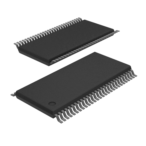


Common questions
Product FAQ
Targeted answers for buyers verifying the exact CD4097BE ordering code, packaging, stock, datasheet, and replacement path.
What does CD4097BE mean?
CD4097BE is the exact ordering code listed for a Interface - Analog Switches, Multiplexers, Demultiplexers component from Texas Instruments. The current package reference is DIP, with listed context including IC MUX/DEMUX DUAL 1X8 24DIP. Buyers should use the full code when requesting stock, price, datasheet, or compliance confirmation.
How should buyers verify the CD4097BE ordering code?
Treat CD4097BE as the full ordering code during RFQ and engineering review. Confirm the listed DIP package, manufacturer documentation from Texas Instruments, datasheet ordering table, reel or packing details, and any customer approval constraints before substitution or PO release.
What package is CD4097BE supplied in?
CD4097BE is currently listed with package reference DIP from Texas Instruments. Buyers should confirm the manufacturer package drawing, footprint, pinout, tape-and-reel details, and receiving requirements before approval.
Is CD4097BE currently available?
CD4097BE is currently marked with stock availability on this page. Before ordering, confirm the package (DIP), listed stock (10965), available quantity (10965), required quantity, lead time, final price, compliance needs, and exact ordering code match through RFQ.
Where can I compare CD4097BE alternatives?
A mapped alternative list is not currently published for CD4097BE. Send an RFQ with the target quantity, package constraints, and approval requirements so TrustCompo can help review credible replacement options.