
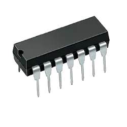
CY7C63813-PXC Interface - Controllers by Cypress Semiconductor
CY7C63813-PXC is a Interface - Controllers from Cypress Semiconductor in DIP packaging. It is commonly reviewed for IC USB PERIPHERAL CTRLR 18-DIP. This page lists current TrustCompo stock, tier pricing, package data, datasheet access, compliance attributes, Hong Kong warehouse shipping options, payment confirmation, and RFQ options for buyers verifying this exact ordering code.
Pictures are for reference only. Please contact us for the latest pictures.
- 365-Day GuaranteeAfter-sales support helps buyers handle quality questions with a clearer return and review window.
- Ships within 24-48 HoursAvailable items can move quickly once the quote, quantity, and delivery details are confirmed.
- 100% Anti-Counterfeit TestedParts are checked through authenticity-focused handling and inspection before shipment.
Key specifications
- Part Number
CY7C63813-PXC
- Internal code
TCE000106186
- Package
DIP
- Manufacturer
- Cypress Semiconductor
Key specifications
- Series
*
- Min Quantity
1
- Category
- Integrated Circuits (ICs)
- Sub Category
- Interface - Controllers
- Description
IC USB PERIPHERAL CTRLR 18-DIP
- key Attributes
-
- Datasheet
- View CY7C63813-PXC Datasheet
Trust signals
Quality and trust signals
Review TrustCompo quality credentials, traceability support, anti-counterfeit handling, and inspection controls before sending an RFQ.
4 certifications
ISO 9001
Quality management processes for more consistent sourcing and handling.
AS9120B
Aerospace-focused distribution controls for traceability and reliability.
ISO 14001
Environmental management discipline across warehouse and operating workflows.
ESD Control
Electrostatic handling standards to help protect sensitive components.
RFQ checklist
Order process
Confirm the core buying details for CY7C63813-PXC before RFQ, PO release, and shipment planning.
- 1
Confirm MPN
Use the exact part number, manufacturer, package, and approval constraints in the RFQ.
- 2
Check stock and price
Verify live availability, MOQ, lead time, final unit price, and tax terms before PO release.
- 3
Align documents
Confirm datasheet, CoC, traceability, lifecycle notes, and inspection scope when required.
- 4
Arrange shipment
Release the PO and align DHL, FedEx, UPS, or buyer forwarder shipment from Hong Kong.
Before PO release
Part confirmation
- Exact MPN confirmed: CY7C63813-PXC
- Package to verify: DIP
Commercial confirmation
- Live stock and lead time confirmed by RFQ
- Final price and tax terms confirmed before PO release
Fulfillment & documents
- Ship-from location: Hong Kong warehouse
- Shipping method: DHL, FedEx, UPS, or buyer forwarder account
Technical parameters
Parameters
Compare grouped CY7C63813-PXC parameters from Cypress Semiconductor, including package, series, key attributes, and technical values used for engineering and sourcing review.
Package Parameter
Height Seated (Max)
4.826mm
Export Classifications & Environmental
Moisture Sensitivity Level (MSL)
1 (Unlimited)
Export Classifications & Environmental
RoHS Status
ROHS3 Compliant
Export Classifications & Environmental
JESD-609 Code
e4
Export Classifications & Environmental
HTSUS
8542.31.0001
Product Parameter
Terminal Finish
Nickel/Palladium/Gold (Ni/Pd/Au)
| Parameter | Value |
|---|---|
Height Seated (Max) Maximum vertical dimension from the seating plane to the top of the component body. Critical for PCB clearance and enclosure fit. Verify against the datasheet when designing mechanical constraints or checking compatibility with mating parts. | 4.826mm |
| Parameter | Value |
|---|---|
Moisture Sensitivity Level (MSL) Indicates the floor life of a component before it must be baked prior to soldering. Higher levels require stricter handling and shorter exposure times. Verify the MSL rating in the datasheet to ensure proper storage and assembly conditions. | 1 (Unlimited) |
RoHS Status Indicates whether the component complies with the EU RoHS directive restricting hazardous substances. Buyers should verify this status for regulatory compliance and market access. Check the datasheet or certificate for exact compliance details. | ROHS3 Compliant |
JESD-609 Code This code indicates the terminal finish material per JESD-609 standard. It helps identify the plating type for soldering compatibility and environmental compliance. Check the datasheet for the exact code and its meaning. | e4 |
HTSUS Harmonized Tariff Schedule of the United States code for customs classification. Essential for import/export documentation and duty calculation. Verify the correct code with a trade specialist to avoid customs delays. | 8542.31.0001 |
| Parameter | Value |
|---|---|
Terminal Finish Specifies the plating material on component terminals, affecting solderability, corrosion resistance, and long-term reliability. Compare finishes like tin, gold, or silver for your assembly process and environmental requirements. Verify against datasheet for compliance. | Nickel/Palladium/Gold (Ni/Pd/Au) |
RAM Size Specifies the amount of random access memory available for data storage during operation. This determines the complexity of tasks the component can handle. Buyers should verify that the RAM size meets the application's memory requirements, especially for real-time processing or buffering. | 256B |
Core Architecture Specifies the processor core design, such as ARM Cortex-M or RISC-V. This determines instruction set compatibility, development tools, and software ecosystem. Verify against the datasheet to ensure firmware and RTOS support match your application requirements. | M8C |
Number Of Channels Specifies how many independent signal paths or outputs the component provides. Compare this value with your circuit requirements to ensure each channel can be used separately. Verify the channel configuration in the datasheet, as some devices may share pins or have internal connections. | 1 |
Bit Size Specifies the number of bits in a single data word for digital components. This determines the maximum data width the device can process or store. Compare bit sizes when selecting microcontrollers, ADCs, DACs, or memory chips to ensure compatibility with your system's data bus and processing requirements. | 8 |
DMA Channels Number of independent direct memory access channels available on the microcontroller or processor. Compare this when selecting devices for data-intensive applications to ensure sufficient bandwidth for peripherals without CPU load. Verify against the datasheet for exact channel mapping and features. | NO |
Power Supplies Specifies the required power supply voltages for the component. Engineers use this to ensure the board's power rails match the device's needs. Verify against the datasheet's recommended operating conditions to avoid undervoltage or overvoltage issues. | 5V |
DAC Channels Number of digital-to-analog converter channels integrated in the device. Compare this to the number of analog outputs you need in your system. Verify against the datasheet to ensure the DAC resolution and output drive capability match your application requirements. | NO |
Has ADC Check this attribute to confirm whether the component integrates an analog-to-digital converter. This is critical for microcontrollers, sensors, and mixed-signal ICs where analog inputs need digital processing. Verify against the datasheet to ensure the ADC meets your resolution and sampling requirements. | NO |
CPU Family Identifies the processor architecture or family, such as ARM Cortex-M or RISC-V. This determines the instruction set, development tools, and software compatibility. Ensure the family matches your existing codebase and toolchain to minimize development effort and risk. | M8C |
PWM Channels Number of independent pulse-width modulation outputs available on the component. Compare this when selecting microcontrollers, motor drivers, or LED controllers to ensure enough channels for your application. Verify against the datasheet for channel mapping and shared timer limitations. | NO |
ROM Programmability Indicates whether the read-only memory can be programmed or is factory-fixed. Buyers should verify if the device supports one-time or field programming, and check the datasheet for programming voltage and timing requirements. | FLASH |
Supply Voltage Specifies the range of DC or AC input voltage the component requires for proper operation. Engineers compare this to the system power rail to ensure compatibility. Always verify against the datasheet's absolute maximum ratings to prevent damage. | 4V~5.5V |
Function Specifies the logical or operational function of the component, such as switching, amplification, or regulation. This attribute helps identify the device's role in a circuit. Verify the function against the datasheet to ensure it matches your application requirements. | Controller |
| Parameter | Value |
|---|---|
Part Status Lifecycle status of the part, such as active or obsolete. Indicates availability and long-term support from the manufacturer. Check this before design-in to avoid last-time buys or supply disruptions. Verify with the datasheet or distributor for current status. | Active |
REACH Status Shows whether the component complies with the EU REACH regulation. Essential for legal market access in Europe. Check the manufacturer's latest statement to confirm that no substances of very high concern are present above the threshold. | REACH Unaffected |
Lead Free Indicates whether the component is manufactured without lead, complying with RoHS and similar regulations. Check this attribute to ensure environmental compliance for your market. Verify against the datasheet for exact material declarations. | Lead Free |
Packaging Indicates the form of delivery for the component, such as tape and reel, tube, or tray. This affects handling, storage, and assembly processes. Verify the packaging type matches your production requirements and equipment compatibility. | Tube |
Published Published indicates the date when the product data was released or updated in the catalog. It helps buyers assess the freshness of the information and whether the component is current or possibly obsolete. Check the datasheet for the latest revisions. | 2004 |
Factory Lead Time Indicates the typical duration from order confirmation to shipment from the manufacturer's facility. This helps you plan production schedules and inventory. Verify current lead times with your distributor or supplier, as they may vary based on order quantity, product availability, and market conditions. | 10 Weeks |
Categories Lists the product categories or classifications assigned to this component, such as connectors, capacitors, or modules. This helps in filtering and comparing similar parts. Review the categories to ensure the component fits your application and to find alternative parts in the same class. | Integrated Circuits (ICs) |
Terminal Position Position of the terminals on the package, such as dual-in-line, gull-wing, or J-lead. This affects PCB layout, soldering, and thermal performance. Engineers must ensure the terminal position matches the footprint and assembly capabilities of their manufacturing line. | DUAL |
Peak Reflow Temperature (Cel) Maximum temperature during reflow soldering that the component can withstand. This is critical for solder joint reliability and preventing damage. Verify that the peak reflow temperature is compatible with your soldering profile and the component's moisture sensitivity level. | 260 |
Supply Voltage Specifies the nominal operating voltage that must be applied to the component for proper function. Verify this value against your system's power rail and the datasheet's absolute maximum ratings to ensure reliable operation and avoid damage. | 5V |
Technology Manufacturing technology or process used for the component, such as thin film, thick film, or semiconductor process. Affects performance, stability, and cost. Confirm the technology matches your application requirements and environmental conditions. | CMOS |
Series Indicates the product series or family, grouping components with similar design and specifications. Helps identify compatible parts and compare within a product line. Verify the series against the datasheet to ensure correct application. | * |
Data Rate Specifies the maximum data transfer rate the component can handle, typically in bits per second. Compare this value with your system's required throughput to ensure adequate bandwidth. Verify against the datasheet for exact conditions and supported protocols. | 1.5 Mbps |
Operating Temperature Specifies the ambient temperature range within which the component reliably functions. Compare this with your application's thermal environment to ensure proper operation. Always verify against the datasheet for derating curves and maximum ratings. | 0°C~70°C |
Frequency Operating frequency of the component, typically the clock or switching frequency. This determines the speed of operation and affects power dissipation and signal integrity. Verify the frequency range against your application's requirements and the datasheet specifications. | 24MHz |
Package / Case Physical package or case type of the component, defining its dimensions, mounting style, and thermal characteristics. Common types include SMD, through-hole, BGA, and QFN. Choose the package that fits your PCB layout and assembly process. Verify the exact package code in the datasheet for footprint compatibility. | 18-DIP (0.300, 7.62mm) |
Reflow Temperature-Max (S) Maximum time the component can be exposed to the peak reflow temperature during soldering. Exceeding this duration may cause damage or degrade reliability. Ensure your soldering profile stays within this limit and check the datasheet for exact conditions. | 30 |
Radiation Hardening Indicates if the component is designed to withstand ionizing radiation in space, nuclear, or high-energy physics applications. Compare radiation-tolerant vs. radiation-hardened parts for mission-critical designs. Verify the total ionizing dose (TID) and single-event effect (SEE) ratings in the datasheet. | No |
Pb-Free Code Indicates whether the component is lead-free per RoHS or other directives. Buyers use this to verify environmental compliance and avoid restricted substances. Always confirm with the datasheet or certificate of compliance. | yes |
Manufacturer Identifies the company that designed and produced the component. Buyers often filter by manufacturer to ensure brand reliability, quality standards, and supply chain consistency. Verify the manufacturer against the datasheet and official packaging to avoid counterfeit parts. | Cypress Semiconductor |
Number Of I/O Total number of input/output pins or channels available on the device. Determines connectivity and interface capability. Verify against your system requirements and datasheet to ensure sufficient I/O for your application. | 16 |
Surface Mount Mounting type: surface mount or through-hole. Surface mount components are placed directly on the PCB, saving space and enabling automated assembly. Through-hole components offer stronger mechanical bonds. Verify the mounting style matches your PCB design and assembly process. | NO |
Terminal Pitch Terminal pitch is the center-to-center distance between adjacent leads or pads on a component. It determines PCB layout compatibility and soldering feasibility. Verify against the datasheet to ensure your footprint matches the component's actual lead spacing. | 2.54mm |
Number Of Terminations Indicates the total number of electrical connection points on the component, such as pins or pads. This is critical for PCB footprint design and assembly. Verify it matches the package specification to ensure proper soldering and connectivity. | 18 |
Number Of Pins Total number of pins or contacts on the component. This determines the footprint and mating connector requirements. Always match the pin count to your PCB layout and connector specification to ensure proper electrical and mechanical connection. | 18 |
Width Physical width of the component body, typically in millimeters. Essential for PCB footprint design and mechanical fit. Verify against the datasheet to ensure proper clearance and compatibility with your board layout and enclosure. | 7.62mm |
Operating Supply Voltage Specifies the voltage range within which the component operates correctly. Check the datasheet to ensure your power supply meets the minimum and maximum limits, as exceeding them can damage the device or cause malfunction. | 5.5V |
Terminal Form Describes the physical configuration of the component's leads or pads, such as through-hole, surface mount, or gull-wing. This affects PCB layout, soldering process, and mechanical fit. Confirm compatibility with your assembly method and footprint. | THROUGH-HOLE |
Weight Specifies the physical weight of the electronic component, important for logistics, shipping cost, and mechanical design. Verify the exact weight in the datasheet or packaging information, as it may vary with packaging type and quantity. | 1.270087g |
ECCN Export Control Classification Number assigned by the U.S. government. Determines whether the component requires an export license. Essential for international trade compliance. Verify the ECCN with the manufacturer or supplier before shipping to avoid legal issues. | 3A991A3 |
Operating Supply Current The amount of current the device draws from its power supply during normal operation. This is essential for power budget calculations, thermal management, and selecting appropriate power sources. Check datasheet for typical and maximum values under specified conditions. | 40mA |
Sub-Categories Indicates the specific product subcategories or classifications within the broader component family. Helps narrow down search results and identify the exact type of component needed for your design. Review the subcategory to ensure compatibility with your application. | Interface - Controllers |
Length Specifies the physical length of the component body, typically in millimeters. This dimension is critical for PCB layout and mechanical fit. Verify against the datasheet to ensure proper clearance and alignment in your design. | 22.733mm |
Manufacturer'S Part No. The unique part number assigned by the original component manufacturer. Use this to cross-reference datasheets, verify specifications, and ensure the exact component matches your design requirements. Always confirm the number against the manufacturer's official documentation. | CY7C63813-PXC |
Base Part Number Identifies the core product family without package, grade, or option suffixes. Use this to compare equivalent components across manufacturers and to locate the primary datasheet. Verify the full ordering code against the manufacturer's specification before design-in. | CY7C63813 |
Standards Indicates compliance with industry standards such as IPC, JEDEC, or UL. Verify the specific standard and revision against the datasheet to ensure the component meets your application's regulatory and quality requirements. | USB 2.0 |
Interface Specifies the communication protocol or interface type used by the component, such as I2C, SPI, UART, or USB. This determines how the device connects to a microcontroller or system. Verify compatibility with your host controller and bus voltage levels before design-in. | GPIO, SPI |
Protocol Communication protocol supported by the device, such as I2C, SPI, UART, CAN, or USB. This determines how the component interfaces with microcontrollers or other system devices. Ensure compatibility with your system's bus architecture and check protocol version and features in the datasheet. | USB |
Datasheet preview
Datasheet PDF viewer
Preview the CY7C63813-PXC datasheet from Cypress Semiconductor to check package, electrical characteristics, application notes, and document evidence before RFQ.
Cypress Semiconductor
CY7C63813-PXC
Page 1 of 0 / —
Loading PDF viewer...
Notice documents
PCN / product notice documents
0 documents
No public PCN / PDN records currently displayed
No public product notice document is currently displayed for CY7C63813-PXC. Confirm PCN, PDN, EOL, date code, and lifecycle status during RFQ before production purchase.
Related sourcing options
Recommended products
Explore related Interface - Controllers products to compare fit, stock status, datasheets, and sourcing options.
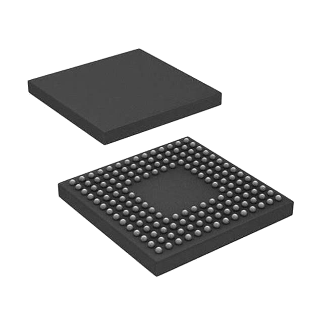
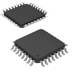
 KSZ9563RNXI128 purchasedVQFN-64
KSZ9563RNXI is an Ethernet switch controller example used in this lifecycle-response article and staged here for product-link coverage.
Reference priceNeeds inquiry
Common questions
Product FAQ
Targeted answers for buyers verifying the exact CY7C63813-PXC ordering code, packaging, stock, datasheet, and replacement path.
What does CY7C63813-PXC mean?
CY7C63813-PXC is the exact ordering code listed for a Interface - Controllers component from Cypress Semiconductor. The current package reference is DIP, with listed context including IC USB PERIPHERAL CTRLR 18-DIP. Buyers should use the full code when requesting stock, price, datasheet, or compliance confirmation.
How should buyers verify the CY7C63813-PXC ordering code?
Treat CY7C63813-PXC as the full ordering code during RFQ and engineering review. Confirm the listed DIP package, manufacturer documentation from Cypress Semiconductor, datasheet ordering table, reel or packing details, and any customer approval constraints before substitution or PO release.
What package is CY7C63813-PXC supplied in?
CY7C63813-PXC is currently listed with package reference DIP from Cypress Semiconductor. Buyers should confirm the manufacturer package drawing, footprint, pinout, tape-and-reel details, and receiving requirements before approval.
Is CY7C63813-PXC currently available?
CY7C63813-PXC is currently marked with stock availability on this page. Before ordering, confirm the package (DIP), listed stock (29931), available quantity (16931), required quantity, lead time, final price, compliance needs, and exact ordering code match through RFQ.
Where can I compare CY7C63813-PXC alternatives?
A mapped alternative list is not currently published for CY7C63813-PXC. Send an RFQ with the target quantity, package constraints, and approval requirements so TrustCompo can help review credible replacement options.