
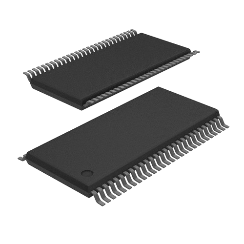
TS5A3153DCURG4 Interface - Analog Switches, Multiplexers, Demultiplexers by Texas Instruments
TS5A3153DCURG4 is a Interface - Analog Switches, Multiplexers, Demultiplexers from Texas Instruments in manufacturer-listed packaging. It is commonly reviewed for IC SWITCH SPDT US8. This page lists current TrustCompo stock, tier pricing, package data, datasheet access, compliance attributes, Hong Kong warehouse shipping options, payment confirmation, and RFQ options for buyers verifying this exact ordering code.
Pictures are for reference only. Please contact us for the latest pictures.

- 365-Day GuaranteeAfter-sales support helps buyers handle quality questions with a clearer return and review window.
- Ships within 24-48 HoursAvailable items can move quickly once the quote, quantity, and delivery details are confirmed.
- 100% Anti-Counterfeit TestedParts are checked through authenticity-focused handling and inspection before shipment.
Key specifications
- Part Number
TS5A3153DCURG4
- Internal code
TCE000092019
- Package
-
- Manufacturer
- Texas Instruments
Key specifications
- Series
-
- Min Quantity
1
- Category
- Integrated Circuits (ICs)
- Description
IC SWITCH SPDT US8
- key Attributes
-
Trust signals
Quality and trust signals
Review TrustCompo quality credentials, traceability support, anti-counterfeit handling, and inspection controls before sending an RFQ.
4 certifications
ISO 9001
Quality management processes for more consistent sourcing and handling.
AS9120B
Aerospace-focused distribution controls for traceability and reliability.
ISO 14001
Environmental management discipline across warehouse and operating workflows.
ESD Control
Electrostatic handling standards to help protect sensitive components.
RFQ checklist
Order process
Confirm the core buying details for TS5A3153DCURG4 before RFQ, PO release, and shipment planning.
- 1
Confirm MPN
Use the exact part number, manufacturer, package, and approval constraints in the RFQ.
- 2
Check stock and price
Verify live availability, MOQ, lead time, final unit price, and tax terms before PO release.
- 3
Align documents
Confirm datasheet, CoC, traceability, lifecycle notes, and inspection scope when required.
- 4
Arrange shipment
Release the PO and align DHL, FedEx, UPS, or buyer forwarder shipment from Hong Kong.
Before PO release
Part confirmation
- Exact MPN confirmed: TS5A3153DCURG4
- Package to verify: -
Commercial confirmation
- Live stock and lead time confirmed by RFQ
- Final price and tax terms confirmed before PO release
Fulfillment & documents
- Ship-from location: Hong Kong warehouse
- Shipping method: DHL, FedEx, UPS, or buyer forwarder account
Technical parameters
Parameters
Compare grouped TS5A3153DCURG4 parameters from Texas Instruments, including package, series, key attributes, and technical values used for engineering and sourcing review.
Product Attribute
Lead Free
Lead Free
Product Attribute
Mounting Type
Surface Mount
Product Attribute
Packaging
Tape & Reel (TR)
Product Attribute
Part Status
Discontinued
Product Attribute
Categories
Integrated Circuits (ICs)
Product Attribute
Terminal Position
DUAL
| Parameter | Value |
|---|---|
Lead Free Indicates whether the component is manufactured without lead, complying with RoHS and similar regulations. Check this attribute to ensure environmental compliance for your market. Verify against the datasheet for exact material declarations. | Lead Free |
Mounting Type Specifies how the component is attached to the PCB, such as through-hole or surface mount. This affects assembly processes, thermal performance, and mechanical strength. Buyers should verify compatibility with their manufacturing capabilities and design requirements. | Surface Mount |
Packaging Indicates the form of delivery for the component, such as tape and reel, tube, or tray. This affects handling, storage, and assembly processes. Verify the packaging type matches your production requirements and equipment compatibility. | Tape & Reel (TR) |
Part Status Lifecycle status of the part, such as active or obsolete. Indicates availability and long-term support from the manufacturer. Check this before design-in to avoid last-time buys or supply disruptions. Verify with the datasheet or distributor for current status. | Discontinued |
Categories Lists the product categories or classifications assigned to this component, such as connectors, capacitors, or modules. This helps in filtering and comparing similar parts. Review the categories to ensure the component fits your application and to find alternative parts in the same class. | Integrated Circuits (ICs) |
Terminal Position Position of the terminals on the package, such as dual-in-line, gull-wing, or J-lead. This affects PCB layout, soldering, and thermal performance. Engineers must ensure the terminal position matches the footprint and assembly capabilities of their manufacturing line. | DUAL |
Peak Reflow Temperature (Cel) Maximum temperature during reflow soldering that the component can withstand. This is critical for solder joint reliability and preventing damage. Verify that the peak reflow temperature is compatible with your soldering profile and the component's moisture sensitivity level. | 260 |
Terminal Form Describes the physical configuration of the component's leads or pads, such as through-hole, surface mount, or gull-wing. This affects PCB layout, soldering process, and mechanical fit. Confirm compatibility with your assembly method and footprint. | GULL WING |
Manufacturer Identifies the company that designed and produced the component. Buyers often filter by manufacturer to ensure brand reliability, quality standards, and supply chain consistency. Verify the manufacturer against the datasheet and official packaging to avoid counterfeit parts. | Texas |
Terminal Pitch Terminal pitch is the center-to-center distance between adjacent leads or pads on a component. It determines PCB layout compatibility and soldering feasibility. Verify against the datasheet to ensure your footprint matches the component's actual lead spacing. | 0.5mm |
Operating Temperature Specifies the ambient temperature range within which the component reliably functions. Compare this with your application's thermal environment to ensure proper operation. Always verify against the datasheet for derating curves and maximum ratings. | -40°C~85°C TA |
Sub-Categories Indicates the specific product subcategories or classifications within the broader component family. Helps narrow down search results and identify the exact type of component needed for your design. Review the subcategory to ensure compatibility with your application. | Interface - Analog Switches, Multiplexers, Demultiplexers |
Subcategory A more specific classification within the main product category, such as 'Ceramic Capacitor' under 'Capacitors'. This helps narrow down search results and compare similar components. Use it to filter products with similar characteristics and intended applications. | Multiplexer or Switches |
Minimum Supply Voltage Specifies the lowest DC input voltage at which the component reliably operates. Compare this value with your system's power rail tolerances and the device's recommended operating conditions to ensure stable performance across all load and temperature ranges. | 1.65V |
Charge Injection Charge injection is the amount of charge transferred into a load during switching. It affects glitch energy and settling accuracy in sample-and-hold circuits. Compare values when selecting analog switches or multiplexers, and verify against the datasheet for your operating conditions. | 12pC |
Package / Case Physical package or case type of the component, defining its dimensions, mounting style, and thermal characteristics. Common types include SMD, through-hole, BGA, and QFN. Choose the package that fits your PCB layout and assembly process. Verify the exact package code in the datasheet for footprint compatibility. | 8-VFSOP (0.091, 2.30mm Width) |
Number Of Functions Specifies the count of independent functions or channels integrated into a single component package. This helps engineers determine if the part can handle multiple signal paths or operations simultaneously. Verify against the datasheet to ensure the device meets your circuit's functional requirements. | 1 |
Radiation Hardening Indicates if the component is designed to withstand ionizing radiation in space, nuclear, or high-energy physics applications. Compare radiation-tolerant vs. radiation-hardened parts for mission-critical designs. Verify the total ionizing dose (TID) and single-event effect (SEE) ratings in the datasheet. | No |
Mounting Type Specifies how the component attaches to the PCB or assembly, such as surface mount, through-hole, or chassis mount. This affects soldering process, mechanical stability, and thermal performance. Verify compatibility with your board layout and assembly capabilities. | Surface Mount |
Pb-Free Code Indicates whether the component is lead-free per RoHS or other directives. Buyers use this to verify environmental compliance and avoid restricted substances. Always confirm with the datasheet or certificate of compliance. | yes |
Number Of Circuits Specifies the total number of independent electrical paths or circuits within the component. This is critical for connectors, switches, and relay arrays to match the required wiring scheme. Always verify against the datasheet to ensure the circuit count meets your application's needs. | 1 |
Number Of Pins Total number of pins or contacts on the component. This determines the footprint and mating connector requirements. Always match the pin count to your PCB layout and connector specification to ensure proper electrical and mechanical connection. | 8 |
Number Of Terminations Indicates the total number of electrical connection points on the component, such as pins or pads. This is critical for PCB footprint design and assembly. Verify it matches the package specification to ensure proper soldering and connectivity. | 8 |
Pin Count Total number of pins or terminals on the component package. Essential for footprint design, PCB layout, and connector mating. Verify against the datasheet to ensure compatibility with your board and assembly process. | 8 |
Max Supply Voltage Indicates the highest DC or AC voltage that can be safely applied to the power supply pin without risking damage or malfunction. Verify this limit against the datasheet before designing your circuit to ensure reliable operation under all conditions. | 5.5V |
Bandwidth Indicates the frequency range over which the component operates effectively. Compare bandwidth when selecting amplifiers, filters, or data converters. Verify the specified bandwidth against your signal frequency requirements and the datasheet's test conditions to ensure optimal performance. | 100MHz |
Supply Voltage Specifies the nominal operating voltage that must be applied to the component for proper function. Verify this value against your system's power rail and the datasheet's absolute maximum ratings to ensure reliable operation and avoid damage. | 1.8V |
Number Of Outputs Specifies how many independent output channels the component provides. Compare this when selecting power supplies, drivers, or modules to ensure the device can drive all required loads. Always verify against the datasheet for exact output configuration. | 2 |
Nominal Supply Current Typical current drawn from the supply under nominal operating conditions. Compare this value across similar components to estimate power consumption and thermal behavior. Always verify against the datasheet for your specific voltage and load conditions. | 20nA |
Resistance Electrical resistance value in ohms, defining opposition to current flow. Critical for current limiting, voltage division, and signal conditioning. Always check tolerance and power rating in the datasheet for reliable circuit operation. | 900mOhm |
Max Supply Current Maximum current drawn from the power supply under specified operating conditions. Compare this value across similar components to estimate power consumption and thermal load. Always verify against the datasheet for your exact supply voltage and load scenario. | 100nA |
Voltage - Supply, Single (V+) Specifies the single positive supply voltage required for the component's operation. This is a key parameter for power design and compatibility. Always verify the absolute maximum ratings and recommended operating range in the datasheet to avoid damage and ensure stable performance. | 1.65V~5.5V |
Weight Specifies the physical weight of the electronic component, important for logistics, shipping cost, and mechanical design. Verify the exact weight in the datasheet or packaging information, as it may vary with packaging type and quantity. | 9.610488mg |
Operating Supply Current The amount of current the device draws from its power supply during normal operation. This is essential for power budget calculations, thermal management, and selecting appropriate power sources. Check datasheet for typical and maximum values under specified conditions. | 20nA |
-3dB Bandwidth Indicates the frequency range where the component's gain or response remains within 3 dB of its nominal value. Engineers compare this to ensure signal fidelity in amplifiers, filters, and communication circuits. Verify against the datasheet for your operating frequency. | 97MHz |
Switch-On Time-Max Specifies the longest interval from applying the control signal until the device conducts or switches on. Compare this value with your timing requirements, especially in power supplies or switching circuits. Verify against the datasheet under specified test conditions, as it affects efficiency and transient response. | 63ns |
Manufacturer'S Part No. The unique part number assigned by the original component manufacturer. Use this to cross-reference datasheets, verify specifications, and ensure the exact component matches your design requirements. Always confirm the number against the manufacturer's official documentation. | TS5A3153DCURG4 |
Switch Time (Ton, Toff) (Max) Maximum turn-on and turn-off time for the switching device. Compare this parameter when evaluating switching speed for power supplies or converters. Verify against the datasheet under specified test conditions to ensure it meets your application's timing requirements. | 16ns, 15ns |
Base Part Number Identifies the core product family without package, grade, or option suffixes. Use this to compare equivalent components across manufacturers and to locate the primary datasheet. Verify the full ordering code against the manufacturer's specification before design-in. | TS5A3153 |
| Parameter | Value |
|---|---|
Height Seated (Max) Maximum vertical dimension from the seating plane to the top of the component body. Critical for PCB clearance and enclosure fit. Verify against the datasheet when designing mechanical constraints or checking compatibility with mating parts. | 0.9mm |
| Parameter | Value |
|---|---|
Mux/Demux Circuit Configuration Defines the switch topology, such as 2:1, 4:1, or 8:1, indicating how many inputs are routed to outputs. Essential for selecting the correct multiplexer for signal routing in your design. Check the datasheet for channel count and switching characteristics. | 2:1 |
Switch Circuit Defines the electrical configuration of a switch, such as SPST, SPDT, or DPDT, indicating how many poles and throws are available. This determines the switching logic and wiring options in your circuit design. Always check the datasheet for contact ratings. | SPDT |
Switching Describes the type or method of switching used by the component, such as latching, momentary, or break-before-make. This attribute defines how the switch or relay operates in the circuit. Check the datasheet to understand the switching mechanism and its suitability for your application. | BREAK-BEFORE-MAKE |
Terminal Finish Specifies the plating material on component terminals, affecting solderability, corrosion resistance, and long-term reliability. Compare finishes like tin, gold, or silver for your assembly process and environmental requirements. Verify against datasheet for compliance. | Nickel/Palladium/Gold (Ni/Pd/Au) |
Off-State Isolation (Nominal) Specifies the nominal resistance between isolated circuits when the component is off. Higher values indicate better isolation and lower leakage. Verify this parameter against the datasheet for applications requiring high voltage or safety isolation. | 64 dB |
Crosstalk Unwanted signal coupling between adjacent channels in a multi-channel device. This parameter indicates how much a signal on one channel can interfere with another. Critical for analog switches, multiplexers, and audio or precision measurement applications. Check datasheet for frequency-dependent behavior. | -64dB @ 1MHz |
Channel-To-Channel Matching (ΔRon) Indicates the maximum difference in on-resistance between any two channels in a multi-channel switch or multiplexer. This parameter affects signal integrity and accuracy in analog routing applications. Compare this value when selecting devices for precision measurement or audio systems. | 50m Ω |
On-State Resistance Match-Nom Indicates the nominal matching of on-state resistance between multiple channels in a device, such as a dual MOSFET or analog switch. This parameter is critical for parallel operation and current sharing. Verify the specified match against the datasheet to ensure balanced performance. | 0.16Ohm |
Receive Delay-Max Maximum time from signal arrival at the receive input to its appearance at the output. Compare this delay across devices to ensure timing margins in your system. Verify against the datasheet for your operating conditions. | 900mOhm |
Number Of Channels Specifies how many independent signal paths or outputs the component provides. Compare this value with your circuit requirements to ensure each channel can be used separately. Verify the channel configuration in the datasheet, as some devices may share pins or have internal connections. | 1 |
Supply Type Indicates the required power source, such as AC or DC, for the component. Engineers compare this to ensure compatibility with the system's power architecture. Verify the supply type against the datasheet to avoid incorrect power connections. | Single |
Number Of Inputs Defines how many input channels the component supports, such as a multiplexer, logic gate, or amplifier. This determines the maximum number of signals that can be routed or processed. Ensure the input count matches your system's channel requirements and pin configuration. | 1 |
Turn-Off Delay Time Measures the time from when the turn-off command is applied to when the device actually begins to switch off. This delay affects switching losses and timing in power circuits. Engineers compare this parameter to ensure proper synchronization and to minimize power dissipation during high-frequency operation. | 19 ns |
Channel Capacitance (CS(Off), CD(Off)) Capacitance between source and drain terminals when the switch is off. This parasitic capacitance affects high-frequency performance, switching speed, and signal integrity. Lower values are preferred for RF and high-speed digital applications. Verify against datasheet for voltage and frequency conditions. | 19pF 36pF |
Turn On Delay Time Time from when the input signal crosses its threshold until the output begins to turn on. This parameter affects switching speed and power dissipation in high-frequency circuits. Verify it against the datasheet for your specific load and drive conditions. | 61 ns |
| Parameter | Value |
|---|---|
RoHS Status Indicates whether the component complies with the EU RoHS directive restricting hazardous substances. Buyers should verify this status for regulatory compliance and market access. Check the datasheet or certificate for exact compliance details. | ROHS3 Compliant |
Moisture Sensitivity Level (MSL) Indicates the floor life of a component before it must be baked prior to soldering. Higher levels require stricter handling and shorter exposure times. Verify the MSL rating in the datasheet to ensure proper storage and assembly conditions. | 1 (Unlimited) |
JESD-609 Code This code indicates the terminal finish material per JESD-609 standard. It helps identify the plating type for soldering compatibility and environmental compliance. Check the datasheet for the exact code and its meaning. | e4 |
Notice documents
PCN / product notice documents
0 documents
No public PCN / PDN records currently displayed
No public product notice document is currently displayed for TS5A3153DCURG4. Confirm PCN, PDN, EOL, date code, and lifecycle status during RFQ before production purchase.
Related sourcing options
Recommended products
Explore related Interface - Analog Switches, Multiplexers, Demultiplexers products to compare fit, stock status, datasheets, and sourcing options.



Common questions
Product FAQ
Targeted answers for buyers verifying the exact TS5A3153DCURG4 ordering code, packaging, stock, datasheet, and replacement path.
What does TS5A3153DCURG4 mean?
TS5A3153DCURG4 is the exact ordering code listed for a Interface - Analog Switches, Multiplexers, Demultiplexers component from Texas Instruments. The current package reference is -, with listed context including IC SWITCH SPDT US8. Buyers should use the full code when requesting stock, price, datasheet, or compliance confirmation.
How should buyers verify the TS5A3153DCURG4 ordering code?
Treat TS5A3153DCURG4 as the full ordering code during RFQ and engineering review. Confirm the listed - package, manufacturer documentation from Texas Instruments, datasheet ordering table, reel or packing details, and any customer approval constraints before substitution or PO release.
What package is TS5A3153DCURG4 supplied in?
TS5A3153DCURG4 is currently listed with package reference - from Texas Instruments. Buyers should confirm the manufacturer package drawing, footprint, pinout, tape-and-reel details, and receiving requirements before approval.
Is TS5A3153DCURG4 currently available?
TS5A3153DCURG4 is currently marked with stock availability on this page. Before ordering, confirm the package (-), listed stock (45453), available quantity (15022), required quantity, lead time, final price, compliance needs, and exact ordering code match through RFQ.
Where can I compare TS5A3153DCURG4 alternatives?
A mapped alternative list is not currently published for TS5A3153DCURG4. Send an RFQ with the target quantity, package constraints, and approval requirements so TrustCompo can help review credible replacement options.