
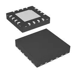
CC3200R1M2RGCR RF Transceiver ICs by Texas Instruments
CC3200R1M2RGCR is a RF Transceiver ICs from Texas Instruments in manufacturer-listed packaging. It is commonly reviewed for IC RF TXRXMCU WIFI 64VFQFN. This page lists current TrustCompo stock, tier pricing, package data, datasheet access, compliance attributes, Hong Kong warehouse shipping options, payment confirmation, and RFQ options for buyers verifying this exact ordering code.
Pictures are for reference only. Please contact us for the latest pictures.
- 365-Day GuaranteeAfter-sales support helps buyers handle quality questions with a clearer return and review window.
- Ships within 24-48 HoursAvailable items can move quickly once the quote, quantity, and delivery details are confirmed.
- 100% Anti-Counterfeit TestedParts are checked through authenticity-focused handling and inspection before shipment.
Key specifications
- Part Number
CC3200R1M2RGCR
- Internal code
TCE000041859
- Package
-
- Manufacturer
- Texas Instruments
Key specifications
- Series
SimpleLink™
- Min Quantity
1
- Category
- RF/IF and RFID
- Sub Category
- RF Transceiver ICs
- Description
IC RF TXRXMCU WIFI 64VFQFN
- key Attributes
-
Trust signals
Quality and trust signals
Review TrustCompo quality credentials, traceability support, anti-counterfeit handling, and inspection controls before sending an RFQ.
4 certifications
ISO 9001
Quality management processes for more consistent sourcing and handling.
AS9120B
Aerospace-focused distribution controls for traceability and reliability.
ISO 14001
Environmental management discipline across warehouse and operating workflows.
ESD Control
Electrostatic handling standards to help protect sensitive components.
RFQ checklist
Order process
Confirm the core buying details for CC3200R1M2RGCR before RFQ, PO release, and shipment planning.
- 1
Confirm MPN
Use the exact part number, manufacturer, package, and approval constraints in the RFQ.
- 2
Check stock and price
Verify live availability, MOQ, lead time, final unit price, and tax terms before PO release.
- 3
Align documents
Confirm datasheet, CoC, traceability, lifecycle notes, and inspection scope when required.
- 4
Arrange shipment
Release the PO and align DHL, FedEx, UPS, or buyer forwarder shipment from Hong Kong.
Before PO release
Part confirmation
- Exact MPN confirmed: CC3200R1M2RGCR
- Package to verify: -
Commercial confirmation
- Live stock and lead time confirmed by RFQ
- Final price and tax terms confirmed before PO release
Fulfillment & documents
- Ship-from location: Hong Kong warehouse
- Shipping method: DHL, FedEx, UPS, or buyer forwarder account
Product overview
Product overview
Review the sourcing context for CC3200R1M2RGCR from Texas Instruments, including product identity, application fit, package notes, and purchasing considerations.
The CC3200R1M2RGCR is a microcontroller unit (MCU) with integrated Wi-Fi capabilities from Texas Instruments. This device is part of the SimpleLink™ Wi-Fi family, which combines high-performance microcontroller functionality with embedded Wi-Fi connectivity. It is designed for easy integration into various IoT (Internet of Things) applications.
Key Features:
- MCU Core: Based on an ARM Cortex-M4 core for powerful processing capabilities.
- Integrated Wi-Fi: Offers built-in Wi-Fi connectivity, supporting 802.11b/g/n standards.
- Flash Memory: Features integrated flash memory for storage of code and data.
- RAM: Includes on-chip RAM for efficient data handling and processing.
- Peripheral Support: Provides various peripheral interfaces such as UART, SPI, I2C, GPIO, ADC, and more.
- Power Management: Designed for low-power operation, suitable for battery-powered applications.
- Security Features: Offers hardware-based security features for secure communication and data protection.
- Development Tools: Compatible with development boards and software development kits (SDKs) for easy application development.
- Package: Available in a compact, space-saving package such as VQFN.
Applications:
- Internet of Things (IoT): Well-suited for a wide range of IoT applications due to its Wi-Fi connectivity and low-power operation.
- Home Automation: Can be used in smart home devices and appliances for wireless connectivity.
- Consumer Electronics: Suitable for integrating wireless capabilities into various consumer electronics.
- Industrial: Applied in industrial control and monitoring systems that require Wi-Fi connectivity.
- Wearable Technology: Can be used in wearable devices for wireless communication and low-power operation.
Technical parameters
Parameters
Compare grouped CC3200R1M2RGCR parameters from Texas Instruments, including package, series, key attributes, and technical values used for engineering and sourcing review.
Product Parameter
Core Architecture
ARM
Product Parameter
Watchdog Timer
Yes
Product Parameter
Has ADC
YES
Product Parameter
PWM Channels
YES
Product Parameter
DAC Channels
NO
Product Parameter
Number Of Timers/Counters
4
| Parameter | Value |
|---|---|
Core Architecture Specifies the processor core design, such as ARM Cortex-M or RISC-V. This determines instruction set compatibility, development tools, and software ecosystem. Verify against the datasheet to ensure firmware and RTOS support match your application requirements. | ARM |
Watchdog Timer Indicates whether the component includes a watchdog timer and its type. This timer resets the system if software hangs, improving reliability. Verify the timeout period and enable/disable options in the datasheet for your application. | Yes |
Has ADC Check this attribute to confirm whether the component integrates an analog-to-digital converter. This is critical for microcontrollers, sensors, and mixed-signal ICs where analog inputs need digital processing. Verify against the datasheet to ensure the ADC meets your resolution and sampling requirements. | YES |
PWM Channels Number of independent pulse-width modulation outputs available on the component. Compare this when selecting microcontrollers, motor drivers, or LED controllers to ensure enough channels for your application. Verify against the datasheet for channel mapping and shared timer limitations. | YES |
DAC Channels Number of digital-to-analog converter channels integrated in the device. Compare this to the number of analog outputs you need in your system. Verify against the datasheet to ensure the DAC resolution and output drive capability match your application requirements. | NO |
Number Of Timers/Counters Specifies how many built-in timer or counter channels are available. These are used for generating precise delays, measuring signal frequencies, or creating PWM signals. Engineers should ensure the count meets the timing requirements of their application, considering each timer's resolution and features. | 4 |
DMA Channels Number of independent direct memory access channels available on the microcontroller or processor. Compare this when selecting devices for data-intensive applications to ensure sufficient bandwidth for peripherals without CPU load. Verify against the datasheet for exact channel mapping and features. | YES |
UART Channel Count Number of independent UART interfaces for serial communication. Each channel supports bidirectional data transfer with configurable baud rate. Ensure the count meets your connectivity needs for peripherals, debugging, or inter-processor links. Verify pin availability in the datasheet. | 2 |
Time At Peak Reflow Temperature (Max) Specifies the maximum duration a component can withstand at the peak reflow temperature during soldering. Critical for evaluating solder joint reliability and preventing thermal damage. Verify against the datasheet's recommended soldering profile to ensure proper assembly. | NOT SPECIFIED |
Bit Size Specifies the number of bits in a single data word for digital components. This determines the maximum data width the device can process or store. Compare bit sizes when selecting microcontrollers, ADCs, DACs, or memory chips to ensure compatibility with your system's data bus and processing requirements. | 32 |
Peak Reflow Temperature-Max (S) Specifies the maximum duration in seconds that a component can withstand at its peak reflow temperature during soldering. Critical for PCB assembly process control to prevent thermal damage. Verify against the datasheet for your specific soldering profile. | Surface Mount |
ROM Programmability Indicates whether the read-only memory can be programmed or is factory-fixed. Buyers should verify if the device supports one-time or field programming, and check the datasheet for programming voltage and timing requirements. | FLASH |
Number Of Programmable I/O Indicates the total number of input/output pins that can be configured by the user. This is critical for FPGA, CPLD, and microcontroller designs. Verify against the datasheet to ensure sufficient I/O for your application. | 27 |
Peripherals Lists the integrated peripheral components such as ADCs, DACs, PWM controllers, comparators, and communication modules. These features reduce external component count and system cost. Engineers should compare available peripherals to ensure they cover all required functions without additional ICs. | I2C |
Supply Voltage Specifies the range of DC or AC input voltage the component requires for proper operation. Engineers compare this to the system power rail to ensure compatibility. Always verify against the datasheet's absolute maximum ratings to prevent damage. | 2.1V~3.6V |
Speed Specifies the maximum clock frequency or data rate of the component. This is critical for timing and performance. Verify the speed grade in the datasheet to ensure it meets your system's throughput requirements and that signal integrity is maintained at that speed. | 80 MHz |
Frequency - Cutoff Or Center Specifies the cutoff or center frequency for filters, oscillators, or resonant circuits. This parameter defines the operating point where signal attenuation or phase shift occurs. Engineers compare this value to ensure the component meets the intended frequency response. Always verify against the datasheet for tolerance and temperature dependence. | YES |
Amplitude Difference (Max) Specifies the maximum allowable deviation in signal amplitude between channels or outputs. Compare this value with the datasheet to ensure balanced performance in differential or multi-channel applications, especially for amplifiers, mixers, or signal conditioning circuits. | Tin |
RAM Size Specifies the amount of random access memory available for data storage during operation. This determines the complexity of tasks the component can handle. Buyers should verify that the RAM size meets the application's memory requirements, especially for real-time processing or buffering. | 256kB |
VSWR-Max Maximum voltage standing wave ratio, indicating how well the component's input impedance is matched to the transmission line. Lower values mean better matching and less signal reflection. Check this parameter when designing RF circuits to ensure minimal power loss and stable operation across the specified frequency range. | 9mm |
| Parameter | Value |
|---|---|
Factory Lead Time Indicates the typical duration from order confirmation to shipment from the manufacturer's facility. This helps you plan production schedules and inventory. Verify current lead times with your distributor or supplier, as they may vary based on order quantity, product availability, and market conditions. | 6 Weeks |
Manufacturer Identifies the company that designed and produced the component. Buyers often filter by manufacturer to ensure brand reliability, quality standards, and supply chain consistency. Verify the manufacturer against the datasheet and official packaging to avoid counterfeit parts. | Texas |
Package / Case Physical package or case type of the component, defining its dimensions, mounting style, and thermal characteristics. Common types include SMD, through-hole, BGA, and QFN. Choose the package that fits your PCB layout and assembly process. Verify the exact package code in the datasheet for footprint compatibility. | 64-VFQFN Exposed Pad |
Thickness Thickness of the component, a critical dimension for PCB clearance, enclosure fit, and thermal performance. This measurement is especially important for capacitors, inductors, and connectors. Ensure the thickness meets your design constraints and does not interfere with adjacent components. Check the datasheet for tolerance and recommended mounting height. | 880μm |
Memory Type Defines the underlying technology used for data storage, such as SRAM, DRAM, or Flash. Determines volatility, speed, and endurance. Choose based on your application's need for persistence and access speed. | ROMless |
Voltage - Rated DC Specifies the maximum DC voltage the component can safely handle under rated conditions. Engineers compare this to the circuit's operating voltage to ensure adequate margin. Always verify against the datasheet's derating curves for temperature and reliability. | SimpleLink™ |
Nominal Supply Voltage (DC) This is the DC voltage at which the component is designed to operate under standard conditions. Compare it with your system's power rail and verify the operating range in the datasheet to ensure reliable performance. | 1mm |
Display Type Specifies the display technology used in the component, such as LCD, OLED, or TFT. This attribute helps engineers select the right module for their application. Verify the exact type and resolution in the datasheet to ensure compatibility with your system. | Lead Free |
Secondary Attributes Lists additional parameters that further define the component's performance or features beyond the primary specifications. Review these attributes to understand special capabilities, limitations, or compliance details that may affect your design, and always confirm them in the manufacturer's datasheet. | ROHS3 Compliant |
Maximum Input VSWR Specifies the highest voltage standing wave ratio allowed at the input port, indicating how well the component matches the transmission line impedance. Lower VSWR means better matching and less reflection. Check this value when designing RF circuits to ensure signal integrity and avoid excessive power loss. | QUAD |
Voltage Indicates the maximum voltage the component can withstand or operate at, depending on context. Critical for ensuring the part is not overstressed in your application. Always compare with your circuit's voltage levels and consider transient spikes. | I2C, SPI, UART |
Ihs Manufacturer Manufacturer name as listed in the IHS database. Use this attribute to identify the original component maker when cross-referencing parts across distributors. Verify the manufacturer to ensure authenticity and traceability, especially for critical or regulated applications. | Nickel/Palladium/Gold (Ni/Pd/Au) |
Series Indicates the product series or family, grouping components with similar design and specifications. Helps identify compatible parts and compare within a product line. Verify the series against the datasheet to ensure correct application. | SimpleLink™ |
Jacket (Insulation) Diameter Outer diameter of the cable jacket or insulation. This dimension is essential for selecting connectors, grommets, and cable glands. Ensure it fits your mechanical design and routing constraints. Verify with the datasheet to avoid assembly issues in tight spaces. | -40°C~85°C |
Preloaded Indicates whether the component comes with preloaded firmware, software, or configuration data. This is relevant for microcontrollers, memory modules, or programmable devices. Verify the preloaded content matches your application requirements to avoid additional programming steps or compatibility issues. | 3.3V |
Brand Name Identifies the manufacturer or brand of the electronic component. Buyers use this to verify authenticity, compare supplier reputation, and ensure compatibility with existing designs. Always check the brand against the datasheet and authorized distributor listings. | 0.5mm |
Secondary Impedance Impedance of the secondary winding or port. This is important for transformers and baluns to ensure proper impedance matching. Mismatched impedance can cause signal reflections and power loss. Check this value against your circuit's load impedance for optimal performance. | 3 (168 Hours) |
Continuous Drain Current (ID) Maximum continuous current the MOSFET can conduct in the on-state without exceeding thermal limits. Compare this rating with your circuit's peak and average current demands. Always verify against the datasheet's thermal resistance and ambient temperature conditions. | CMOS |
Control Voltage-Min Minimum control voltage required for operation. This is essential for devices like VCOs, attenuators, or switches that use voltage control. Ensure your control circuitry can provide at least this voltage to guarantee proper operation across the specified range. | 2.4GHz |
Max. Data Transmission Rate Maximum data transmission rate supported. This is crucial for high-speed communication interfaces. Ensure the component can handle your required throughput with margin. Compare with the datasheet's specifications to avoid bottlenecks in your data path. | Tape & Reel (TR) |
Sub-Categories Indicates the specific product subcategories or classifications within the broader component family. Helps narrow down search results and identify the exact type of component needed for your design. Review the subcategory to ensure compatibility with your application. | RF Transceiver ICs |
Construction Physical construction or design type. This describes the internal architecture or packaging style, such as surface mount, through-hole, or module. It affects mounting, thermal performance, and reliability. Verify that the construction matches your assembly process and application requirements. | e4 |
REACH Compliance Code Indicates the component's compliance status with the EU REACH regulation. Buyers should verify this code against the manufacturer's declaration to ensure restricted substances are within allowable limits for their target market. | yes |
Wire Gauge Specifies the wire size range the connector accepts, typically in AWG. Critical for ensuring proper crimp, current capacity, and mechanical fit. Verify against the connector datasheet to match your wire diameter and insulation thickness. | NO LEAD |
Serial Interfaces List of supported serial communication interfaces, such as SPI, I2C, UART, or CAN. This determines how the component communicates with your system. Verify that the required interfaces are available and compatible with your microcontroller or processor. | I2C, I2S, JTAG, SPI, UART |
Sampling Rate Number of analog signal samples taken per second by an ADC or digital sensor. Determines maximum signal frequency that can be accurately captured. Verify against datasheet for your application's bandwidth needs. | Active |
Typical Power Added Efficiency (%) Typical power added efficiency as a percentage. This indicates how efficiently the component converts DC power to RF output power. Higher efficiency means less heat generation and longer battery life. Compare this value with your system's thermal and power budget. | 260 |
Categories Lists the product categories or classifications assigned to this component, such as connectors, capacitors, or modules. This helps in filtering and comparing similar parts. Review the categories to ensure the component fits your application and to find alternative parts in the same class. | RF/IF and RFID |
Modulation Specifies the modulation scheme used by the component for signal encoding. Compare modulation types to ensure compatibility with your communication protocol and system bandwidth. Verify the supported modulation formats in the datasheet before design-in. | DSSS, OFDM |
Protocol Communication protocol supported by the device, such as I2C, SPI, UART, CAN, or USB. This determines how the component interfaces with microcontrollers or other system devices. Ensure compatibility with your system's bus architecture and check protocol version and features in the datasheet. | 802.11b/g/n |
RF Family/Standard Select the RF standard or family that the component complies with, such as Bluetooth, Wi-Fi, Zigbee, or proprietary protocols. This defines compatibility with existing wireless infrastructure and regulatory certifications. Verify against the datasheet to ensure the device meets your target network requirements. | WiFi |
Manufacturer'S Part No. The unique part number assigned by the original component manufacturer. Use this to cross-reference datasheets, verify specifications, and ensure the exact component matches your design requirements. Always confirm the number against the manufacturer's official documentation. | CC3200R1M2RGCR |
Current - Transmitting Indicates the current consumption or output current during transmission mode. Essential for power budget calculations and thermal management in wireless modules. Check this value against your supply capability and compare with receiving current to estimate battery life. | 53mA~59mA |
UART Indicates support for UART interface. This is a common asynchronous serial protocol for communication between microcontrollers and peripherals. Check this attribute to ensure compatibility with your system's serial communication requirements. | -95.7 dBm |
Conductor Strand Number and configuration of strands in the conductor. This affects flexibility and current carrying capacity. More strands typically provide better flexibility. Ensure the conductor strand configuration meets your mechanical and electrical requirements. | 256kB RAM 64kB ROM |
External Data Bus Width Number of parallel data lines on the external bus. Determines data transfer rate and interface complexity. Important for microcontrollers, DSPs, and memory devices. Verify with datasheet to match your system's bus architecture and timing requirements. | 65536 |
Number Of True Outputs Indicates how many outputs deliver the non-inverted logic state. Compare this with the number of complementary or inverted outputs when selecting logic devices, and verify against the datasheet to ensure the output configuration matches your circuit requirements. | CC3200 |
Number Of I/O Total number of input/output pins or channels available on the device. Determines connectivity and interface capability. Verify against your system requirements and datasheet to ensure sufficient I/O for your application. | 27 |
Number Of Mixers Number of mixers integrated in the component. This is relevant for RF frequency conversion stages. More mixers may indicate support for multiple bands or complex architectures. Verify this count against your signal chain design to ensure the component meets your frequency planning needs. | 9mm |
Maximum Output VSWR Maximum voltage standing wave ratio at the output port. This indicates how well the output impedance matches the load. A lower VSWR means better power transfer and less reflection. Check this value to ensure stable operation with your antenna or transmission line. | 64 |
Current - Receiving Specify the current consumption during receiving operation. This value is critical for battery life estimation in portable devices. Compare it with the datasheet's typical and maximum ratings to ensure your power supply can handle the load under worst-case conditions. | 53mA~59mA |
Power - Output Output power rating of the component. This is critical for amplifiers, transmitters, and power supplies. Ensure the component can deliver the required power to your load without exceeding its ratings. Check the datasheet for conditions and tolerances. | 18.3dBm |
Suitable For Wall Mounting Indicates whether the component can be mounted on a wall. This is relevant for enclosures, antennas, or modules designed for fixed installation. Check this attribute to ensure the product meets your installation requirements and that appropriate mounting hardware is included or specified. | 64 |
Data Rate (Max) Maximum data transfer rate supported. This is crucial for high-speed communication interfaces. Ensure the component can handle your required throughput with margin. Compare with the datasheet's specifications to avoid bottlenecks in your data path. | 54Mbps |
Usage Intended application or usage of the component. This helps identify the target market and typical use cases, such as automotive, industrial, or consumer electronics. Verify that the component's specifications align with your application's environmental and performance requirements. | ACTIVE (Last Updated: 1 day ago) |
Notice documents
PCN / product notice documents
0 documents
No public PCN / PDN records currently displayed
No public product notice document is currently displayed for CC3200R1M2RGCR. Confirm PCN, PDN, EOL, date code, and lifecycle status during RFQ before production purchase.
Related sourcing options
Recommended products
Explore related RF Transceiver ICs products to compare fit, stock status, datasheets, and sourcing options.
Common questions
Product FAQ
Targeted answers for buyers verifying the exact CC3200R1M2RGCR ordering code, packaging, stock, datasheet, and replacement path.
What does CC3200R1M2RGCR mean?
CC3200R1M2RGCR is the exact ordering code listed for a RF Transceiver ICs component from Texas Instruments. The current package reference is -, with listed context including IC RF TXRXMCU WIFI 64VFQFN. Buyers should use the full code when requesting stock, price, datasheet, or compliance confirmation.
How should buyers verify the CC3200R1M2RGCR ordering code?
Treat CC3200R1M2RGCR as the full ordering code during RFQ and engineering review. Confirm the listed - package, manufacturer documentation from Texas Instruments, datasheet ordering table, reel or packing details, and any customer approval constraints before substitution or PO release.
What package is CC3200R1M2RGCR supplied in?
CC3200R1M2RGCR is currently listed with package reference - from Texas Instruments. Buyers should confirm the manufacturer package drawing, footprint, pinout, tape-and-reel details, and receiving requirements before approval.
Is CC3200R1M2RGCR currently available?
CC3200R1M2RGCR is currently marked with stock availability on this page. Before ordering, confirm the package (-), listed stock (103716), available quantity (75689), required quantity, lead time, final price, compliance needs, and exact ordering code match through RFQ.
Where can I compare CC3200R1M2RGCR alternatives?
A mapped alternative list is not currently published for CC3200R1M2RGCR. Send an RFQ with the target quantity, package constraints, and approval requirements so TrustCompo can help review credible replacement options.